This thread has been locked.

If you have a related question, please click the "Ask a related question" button in the top right corner. The newly created question will be automatically linked to this question.

TPS1641: Output negative pulse with about 20mV drop of TPS16413

Part Number: TPS1641

Tool/software:

Hi team,

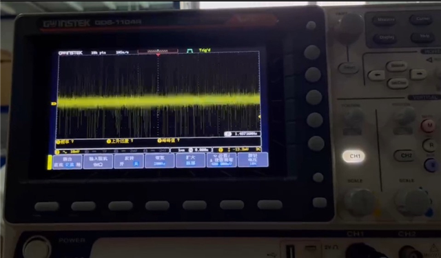
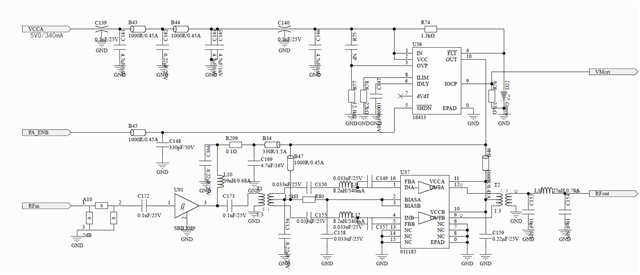
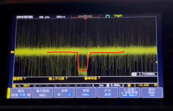
My customers are using TPS16413 and are facing a problem. As you can see in the schematic, the input is about 5V and the Ilim is set up to around 450mA. When the load is connected and the load current is around 370mA (IOCP pin voltage is measured 0.61V), the output voltage seemed to have a negative pulse with 30mV voltage drop, like showed in figure 2 waveform. This voltage drop happened periodically and the customers don't want to see this. They have tried to add a 470uF capacitor on the output pin, while the waveform became a sudden drop with 30mV and slowly ramp up to normal output (sorry that they didn't capture this).

Could you give some suggestions on why this negative pulse occurred and how to eliminate this negative pulse?
BR,

Manu

  • Hello Manu,

    Can you provide some background information 
    1. Negative pulse on output is occurring how long after loading? Is it always observed or sometimes?
    2.Do you or the customer have (VIN) input waveform while Vout drop is happening?  

    Thank You

  • Hi Jit

    Thanks for your reply. Here are my answers:

    1. Negative pulse on output is occurring how long after loading? Is it always observed or sometimes?

    Once the load is added, the neg pulse occurred. Customers have tried to adjust the load current down to 100mA, the pulse still occurred. When no load, this pulse didn't occur. It is always observed, so customers considered as a problem and would like to figure out why. 

    2.Do you or the customer have (VIN) input waveform while Vout drop is happening? 

    Unfortunately they only have a screen shot for Vin, but it showed that there is normal for the Vin and at the meantime Vout had a neg pulse. 

    Pls give some suggestions on the potential root cause of this problem, thanks. 

    BR,

    Manu

  • Hello Manu,

    Thank you for your response.

    It looks like OUT pin is connected to RF signal buffer circuit.

    I have these questions

    1.Are you testing the eFuse separately by disconnecting it from extended circuitry? Please check the eFuse separately.

    Once the load is added, the neg pulse occurred

    2.What is the load type? Please check with passive resistive load.

    Check the input current and FLT to check any kind of fault has happened 

    Thank You

    Amrit 

  • Hi Amrit,

    Thanks for rapid reply and yes the OUT pin is connect to the RF Amplifier. 

    Like I said, when testing separately, namely no load on eFuse. The output seems normal. Once adding load, the neg pulse occurred with about 400kHz frequency. 

    The load type is not fully resistive load for sure, would this be a problem for this device? Customers current test environment may not able to achieve adding a passive resistive load. During the whole tests (no load & with load), They hadn't seen the FLT pin turn to low (namely the LED on FLT pin twinkled).

    Based on current description, can you give some assumptions/explanation on why the neg pulse may possible happen? This may help me and my customers a lot and we can see how to verify them and fix this problem.

    Thanks.

    BR,

    Manu

  • Hey Manu,

    This high frequency pulse could be coming from the RF signal.

    I can see there is a LC filter connected after U91 which is connected to the output cap of eFuse.

    Can the Low pass LC filter parameters be tuned to suppress the 400kHz noise?

    Since the input signal is clean, I don't see any issue with eFuse.

    Thanks

  • Hi Amrit,

    Here are some updates test results from customers.

    1. They didn't connect the TPS16413 and add a separate 5V to the pin10 point (original output of efuse, but not mounting efuse), the neg pulse didn't occur. The RF circuit worked normally and the RF signal looked normal. 

    2. They added TPS16413 back and changed the load to pure resistive load (2x22ohm in parallel), load is about 11ohm and the output current is about 500mA. For not triggering the over current, they changed R78 to 15kohm and R76 to 22kohm. In this case the Ilim should be 656mA and Iocp should be 748mA. No overcurrent event with a 500mA load. They measured the input current (yellow waveform) and output voltage of TPS16413 (blue waveform). As you can see as below, the current has about 28mA increase while the output voltage have about 15mV drop. 

    Based on 2 tests above, it seems that the unexpected voltage drop comes from the TPS14613 itself, but not from the RF signal. Could you pls help to explain why this neg pulse on output might happen and how to avoid this? If this is not solved, customers may consider using other devices. 

    Thanks a a lot.

    BR,

    Manu

  • Hello Manu,

    They have tried to add a 470uF capacitor on the output pin, while the waveform became a sudden drop with 30mV

    Did they with ceramic or electrolytic capacitors ?

    Putting a ceramic cap right next to output will help.

    Electrolytic will not respond to 400kHz ferq voltage change.

    Thanks