


Tool/software:
Hi everyone,
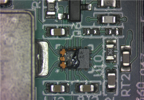
I designed a BMS board where the Vcc line (+5 V) issupplied by the main board DC/DC converter, the LM60440A. The LM60440A (U10) had a clear failure and almost all the IC supplied from the Vcc line seems to have some issue (they're in short-circuits or drain high currents). It seems an overvoltage affected the Vcc line.
At the time of the failure, the buck converter has an input voltage of about 24V. The typical load is less than 0.5A.
I canno find any external cause that leads to this failure. This is a prototype board and I have no any similar fault on the filed.
Any ideas on "how to perform a failure analisys on my board" ?
I suspect that the internal mosfet goes in short bringing the 24Vin to the output. Is it possible something like this could have happened? How can i stress my board to repeat the failure ?
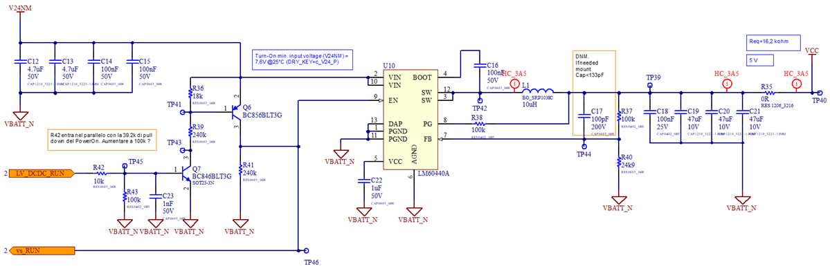
This is the circuit of my DC/DC. Note that I use the 100pF Cff capacitor (C17) despite I wrote to do not mount this on the first prototype boards. This could lead the IC to the instability and cause the failure?
Thank you
