Tool/software:
Please experts in the house help! My design is based on the EVM board and for testing i have the following settings as per
the sample code for STM32. I am a novice, please forgive my desgin quality.
BQ769x2_SetRegister(PowerConfig, 0x2D80, 2);
BQ769x2_SetRegister(REG0Config, 0x01, 1);
BQ769x2_SetRegister(REG12Config, 0x0D, 1);
BQ769x2_SetRegister(DFETOFFPinConfig, 0x00, 1);
BQ769x2_SetRegister(ALERTPinConfig, 0x2A, 1);
BQ769x2_SetRegister(VCellMode, 0x801F, 2);
BQ769x2_SetRegister(EnabledProtectionsA, 0xB8, 1);
BQ769x2_SetRegister(DefaultAlarmMask, 0xF882, 2);
BQ769x2_SetRegister(COVThreshold, 0x55, 1);
BQ769x2_SetRegister(OCCThreshold, 0x05, 1);
BQ769x2_SetRegister(OCD1Threshold, 0x0A, 1);
BQ769x2_SetRegister(SCDThreshold, 0x05, 1);
BQ769x2_SetRegister(SCDDelay, 0x03, 1);
BQ769x2_SetRegister(SCDLLatchLimit, 0x01, 1);
BQ769x2_SetRegister(MfgStatusInit, 0x0050, 2);
BQ769x2_SetRegister(FETOptions,0x3F ,1);
I did not add any thermistor yet.
if i read the cell voltages OUTSIDE this loop: I get the correct readings
but the Alarm bit or FULLSCAN bit is never asserted. If i vary the voltages from the
power supply bench i can read all 6 cell voltages correctly and stack voltage.
AlarmBits = BQ769x2_ReadAlarmStatus();
GPIO_PinState buttonState = HAL_GPIO_ReadPin(ALERT_PIN_2_GPIO_Port,ALERT_PIN_2_Pin);
if (AlarmBits & 0x80) { // Check if FULLSCAN is complete. If set, new measurements are available
BQ769x2_ReadAllVoltages();
Pack_Current = BQ769x2_ReadCurrent();
Temperature[0] = BQ769x2_ReadTemperature(TS1Temperature);
Temperature[1] = BQ769x2_ReadTemperature(TS3Temperature);
DirectCommands(AlarmStatus, 0x0080, W); // Clear the FULLSCAN bit
}
If i set the device in TEST mode, FETS control commnad work. Although running CommandSubcommands(DSGTEST);
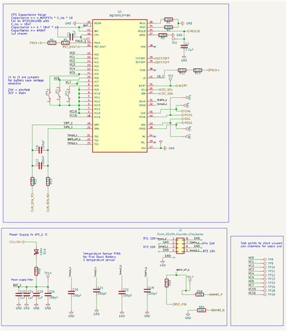
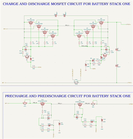
Any ideas why the fullcan bit is never asserted. Charge FET is always on! Attached is my design scehmatics.