This thread has been locked.

If you have a related question, please click the "Ask a related question" button in the top right corner. The newly created question will be automatically linked to this question.

UC2843: Thermal question

Part Number: UC2843
Other Parts Discussed in Thread: UC1843, UC3845, UC2845

Tool/software:

Hi Team,

This is FAE Jayden, my customer is using UC2843DTR in their 12W flybuck power module. My question are below:

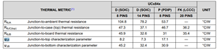
1. After measuring the chip case temperature, should we use the following parameters ψJT to calculate the junction temperature?

2. What is the power loss when the chip is working normally? As my customer test the case temperature is 120C,the device already thermally break down.

3. Why the recommend TA is -40~85C with UC2843, but the max junction temperature is 150C?

Many thanks.

Jayden

  • Hi,

    Please refer to the below application note for their differences.

    Semiconductor and IC Package Thermal Metrics (Rev. D) (ti.com)

    1. Based on this application note, in UC2843 case, I suggest to use Rtheta_jc_top.

     2. You need to know VCC voltage and current and Vc voltage and current to calculate the total power dissipation

    3. In history, UC1843 needs to sustain 150C junction, then any devices cannot pass 150C junction, will be tested at 85C for UC2845, then 70C for UC3845.

  • Hi Hong,

    Thanks. For question 2:

    The VCC is 14V and VC is about 12V, they can't measure the current, Will there be an approximate power loss? ZTE has an old datasheet  that describes static loss. Can this value be used for calculation?

    Brs

    Jayden

  • Hi,

    Vc current can be estimated by the MOSFET gate charge.

    Vcc currently can be estimated by the IC bias current the load on VREF and the error opamp COMP current, also the current needed different at different fosc.

    You can measure the VCC current and Vc current by a current probe or use a few ohm resistor to get rough value and combine with the estimation