This thread has been locked.

If you have a related question, please click the "Ask a related question" button in the top right corner. The newly created question will be automatically linked to this question.

TL431: TL431QDBZRG4 Performance problem

Part Number: TL431

Tool/software:

Hi
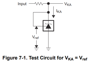
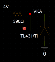
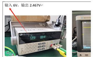
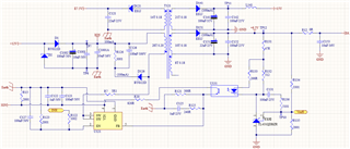
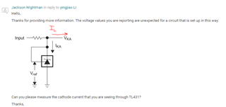
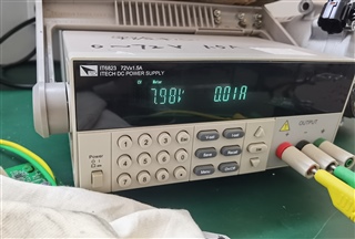
This product we use the same test circuit after the machine, the normal chip input 6 volts and 8 volts. The reference voltage is around 2.46
But 1pcs of them did not meet the test, please help to confirm the reason
thank you  
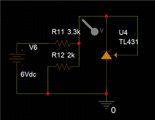
Fail information list_(3).doc

  • Hello,

    Can you explain the purpose of R12 in your schematic? If you remove R12, does the issue persist? If you are looking to get a 2.5 V reference, this schematic should suffice:

    Thanks,

    Jackson

  • Hi
    We have retested according to the above suggestions. The input voltage is different, but the VKA is unstable and the resistance value is 3.3k
    Could you please confirm the reason?
    thank you

  • Hello,

    Can you measure the current across the 3.3kΩ resistor?  Please keep in mind that the minimum cathode current for regulation is 1 mA for TL431, so the current must be greater than that. If you decrease the input resistance or increase the input voltage to make sure that the current is greater than 1mA, does the issue persist?

    Thanks,

    Jackson

  • Hi

    The minimum voltage I give is 4V, 4/3.3k> 1mA, the maximum voltage is 8V, the current is 2.42mA, there are still such anomalies, can I send this back to your company for analysis of the reasons

  • Hello,

    I would suggest decreasing the input resistor to allow a higher input current. The cathode current can be calculated by considering the input voltage (Vin), cathode voltage (VKA), input resistance (Rin), and load current. Please consider below:

    Input current = (Vin-VKA)/Rin. For your application, input current = (4 V- 2.5 V)/3.3kΩ = 455µA or input current = (8V - 2.5V)/3300 = 1.67 mA

    IKA = input current - load current, which means that for 4 V input with 3.3 kΩ, it is impossible for you to stay above 1mA cathode current, and for 8V input with 3.3kΩ, you are only leaving 670µA for your load current. 

    I would suggest decreasing the input resistance to allow a higher input current while keeping in mind the load current that must be available, and then reevaluating. 

  • Hi

    So how small does this decrease in resistance have to be? How much voltage, how much resistance, in order to avoid interference, is it possible to directly fly line test:

  • Hello,

    The decrease in resistance will depend on your load current. For example, assume this is the circuit setup you are using:

    Working backwards, let's say your load current (IL) is 2mA, for example. Since the minimum cathode current for TL431 is 1 mA, I will provide a bit of a buffer to account for any resistor tolerances, and design for a cathode current (IKA) of 1.5 mA. Now, finding the input current, this gives:

    IKA = input current - IL --> Input Current = IKA + IL = 1.5 mA + 2 mA = 3.5 mA

    Now that I have decided the input current is 3.5 mA, I can decide on my input voltage and resistor. Using the input voltage of 4 V, as you have in your application, and assuming that VKA in the figure above is 2.5V based off of its circuit configuration, this gives:

    Input current = (Vin-VKA)/Rin --> Rin = (Vin - VKA)/Input Current = (4V - 2.5V)/3.5mA = 429Ω.

    You can repeat this process for any desired input voltage, input current, cathode current, or input resistance while taking into account your application's load current. Please keep in mind the recommended operating conditions listed in the TL431 datasheet:

    In summary, the required input resistance for proper regulation will vary based off of your desired load current and input voltage.

    Thanks,

    Jackson

  • Hi

    We have provided testing circuits, but they all do not meet the requirements. Then what circuit should we use to test this TL431 to confirm that it is all caused by product anomalies

  • Hello,

    I want to make sure I am understanding completely the issue you are seeing, as it is unclear to me what the b. Can you please provide the following information:

    1. A schematic screenshot of your circuit as it exists on your board with all of the resistor and capacitor values representative of your testing setup, including where the cathode of TL431 connects to. 

    2. Data that clearly lists the following values: Input voltage, input resistance, input current, load current, and cathode voltage. It would be best if you could get multiple data points at different values.

    3. If the output is oscillating, provide a scope capture showing this behavior.

    4. A description of the abnormalities you are seeing.

    Thanks,

    Jackson

  • Hi

    If TL431 is faulty, can this circuit confirm that TL431 under test is faulty

  • Hello,

    The circuit you shared should regulate to 2.5 V, depending on what the load current is.

    1. A schematic screenshot of your circuit as it exists on your board with all of the resistor and capacitor values representative of your testing setup, including where the cathode of TL431 connects to. 

    2. Data that clearly lists the following values: Input voltage, input resistance, input current, load current, and cathode voltage. It would be best if you could get multiple data points at different values.

    3. If the output is oscillating, provide a scope capture showing this behavior.

    4. A description of the abnormalities you are seeing.

    Do you have any additional information on these questions above?

    Thanks,

    Jackson

  • Hi

    Attached is the result of our latest test, please help to confirm it
    thank you

    Fail information list.doc

    Replace the faulty TL431, and the TP10 and TP12 test values are 0

  • Hello,

    Thank you for sharing the schematic. In the document provided, does the "Input" refer to TP12 and "Output" refer to TP10?

    If so, what percentage of total devices are showing this failure?

    Thanks,

    Jackson

  • Hi

    Are you referring to the input for the following tests? This was measured with a separate circuit

    This chip, we've used more than 100,000 of them, and as far as I know this is the first case of failure.
    This time we put into production 3000, and there was one anomaly

  • Hello,

    Thanks for providing more information. The voltage values you are reporting are unexpected for a circuit that is set up in this way:

    Can you please measure the cathode current that you are seeing through TL431?

    Thanks,

    Jackson

  • Hi

    In my application circuit, IL=40~50mA

    No load is drawn in this test circuit in the drawing below. We should be taking what kind of load to test

    Or do we just use this circuit to test I_KA?

    This is for this test circuit, Input takes the current at 6V and 8V respectively

  • Hello,

    No load is drawn in this test circuit in the drawing below. We should be taking what kind of load to test

    If IL=0mA for your test, that is no problem. I am asking about the IKA (cathode current). Please send me the IKA you are seeing for your test setup.

    Thanks,

    Jackson

  • Hi

    When the faulty chip is tested, INPUT=6V, IL=0, IKA= (6-2.7) /390=8.46mA

  • Thank you for confirming the IKA, I will look into the information you provided and get back to you tomorrow.

    Thanks,

    Jackson

  • Hello,

    I have not seen this behavior on my bench and based off of the information you have shared, I have no further recommendations in regards to this issue.

    Thanks,

    Jackson