This thread has been locked.

If you have a related question, please click the "Ask a related question" button in the top right corner. The newly created question will be automatically linked to this question.

TPS51386: Decoupling capacitors miss placement

Part Number: TPS51386

Tool/software:

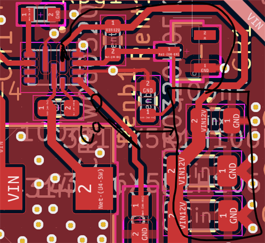
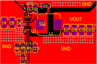
i've miss placed decoupling capacitor 16mm dar from Vin two 10uf and one 0.1uf ,i kow the circuit will amllfunction but will it still work for testing as a first prototype ? 

does the TPS51386 can be forgiving for new designs and bigenner mistakes ? 

  • Hi Firas,

    Did you put them in reverse order? Usually we place the 0.1uF capacitor close to the chip side. Incorrect placement will not directly affect the circuit operation, but it will have some impact on test items where the input voltage is prone to oscillation. Can you place a 0.1uF capacitor close to the chip VIN?

    Looking forward to your reply. Thanks.

    Aurora

  • Thanks Aurora, 

    I had the 0.1uf at first the closed to vin after that the two 10uf, i'll attach some pictures , yes i may be able to put 0.1uf capacitor closer to the vin , but i don't want to scracth the pcb if it's still going to work , and i only need about 3amps max from the circuit So? 

  • I know my circuit is not good enough but i like this to work since i already confirm prototype production, all values and comonents are chosed using TI circuit simulator 

  • Hi,

    Actually, the following is our recommended layout, C6 is 0.1uF capacitor. It looks like this layout is quite different from your current one.

    If the chip currently works, you can use the first version of the circuit for evaluation. When making the next version, please refer to our layout for improvement. Thanks.

    Aurora