This thread has been locked.

If you have a related question, please click the "Ask a related question" button in the top right corner. The newly created question will be automatically linked to this question.

TPS1H200A-Q1: Damage to IC, Vs pin

Part Number: TPS1H200A-Q1

Tool/software:

Hello TI team,

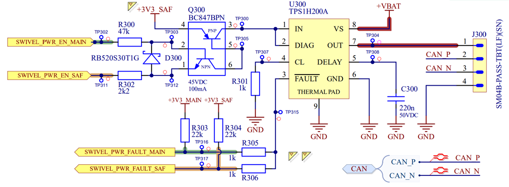
I am wondering if you could assist in an issue we've been having with the TPS1H200AQDGNRQ1 smart high-side switch. We have been using this part in our designs for a while but during a recent implementation on a new board we've encountered an issue. First of all, here is the schematic:


Top layer layout, it's a 4-layer board

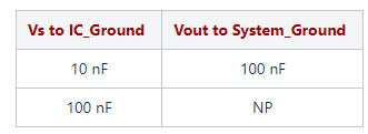
For clarification, on this system we use two MCU's (in the schematics they are differentiated by MAIN / SAF in the label) that both can control the IN pin of the TPS1H200A, likewise they can both read the status of the FAULT pin. This is due to the fact that our system will be certified against the 61508 functional safety standard. To enable (close) the switch, SWIVEL_PWR_EN_MAIN must go HIGH while SWIVEL_PWR_EN_SAF must go LOW. As you can see, a current limit setting and a shut-off delay are also implemented.

All of this is functioning correctly. However, we have now had two instances where the IC blows up upon connecting the batteries to the system (the batteries are directly connected the the VS pin via the +VBAT net label), this does not always happen but when it does (2 times now) the resulting damage is the same, see below.


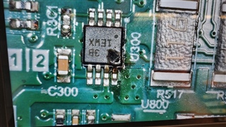
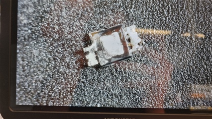
At the moment when we connect the batteries and the damage occurs, there is no load on the OUT pin since we have not connected any cable to J300. At first I expected a one-time (soldering) mistake, but since it has now happened twice I am wondering if something else is wrong.

Do you perhaps see any improvements to due design? Let me know if there is any further information you need.

Thank you!

Maarten

  • Maarten,

    There is nothing explicitly wrong with the schematic, but a couple of notes:

    • I do not see any bypass capacitors in the input/output that would help smooth over transient events and help with EMI. Not quite sure if this is the issue as it appears you might be hotplugging the batteries, but this would help. Our recommended component setup is:

    Since you only have one ground, you connect all capacitors to the same ground. 

    • I do not see any reverse current protection. Generally there is either a diode on the supply side or a ground resistor/diode network. Please refer to 7.3.6.5 Reverse-Current Protection in the datasheet for more information.

    I mentioned above- but are you hot plugging the batteries on the supply side? If there is any sort of bouncing that would cause high input/output voltage surges on the input line this could potentially cause damage as these devices are not exactly built for this application.

    Best Regards,
    Tim 

  • Hello Timothy,

    Thank you for the reply.

    We are actually hot-swapping the battery (large 24VDC nominal batteries), at least during our development phase. And there does indeed not seem to be to much capacitance on the input to smoothen out transients before they reach the TPS1H200A. On other boards were we have the TPS1H200A implemented there are large electrolytic caps on the battery connector, which is probably why we do not have the issue there.

    I do not have the space for large caps on this board so using a TVS is the way to go I think, along with some extra bypass capacitors as you mentioned. I have been looking at the Littelfuse SMF33CA TVS. I cannot go much lower in terms of reverse standoff due to battery charge voltage. The clamping voltage will be ~50V, do you think this will offer enough protection? 

    We do not have any reverse battery protection implemented since by design it is not possible to connect the batteries with reversed polarity, this saves us some costs.  

    Best regards,

    Maarten