This thread has been locked.

If you have a related question, please click the "Ask a related question" button in the top right corner. The newly created question will be automatically linked to this question.

TPS63070: Configured as LED driver - Does not provide expected current

Part Number: TPS63070

Tool/software:

Dear TI,

We are using the TPS63070 as a constant current LED driver, based on the SLVA419D "Different Methods to Drive LEDs Using TPS63xxx Buck-Boost Converters" application report.
The LED to be driven is a SFH 4780S from OSRAM.

The requirements are:

  • Input voltage: 4.2V - 3V (Li-Ion battery powered)
  • LED current drive: 1A ±100mA - but must be stable throughout its input voltage range
  • Pulse drive with a duration of up to 500msec

Our initial design was that shown in page 2 of the SLVA416D but we switched to a simple constant current drive, shown in page 1, since we encountared unexpected results. Despite using the simple drive configuration we are still having the same issue.

The problem that we are facing is that the LED drive current is not what we expect.

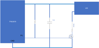
Schematic of the LED driver is shown below.


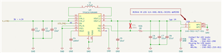
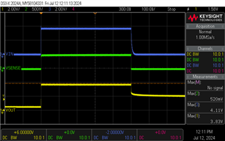
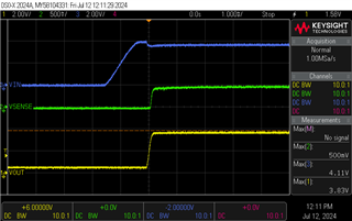
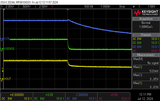
With a typ. feedback voltage of 0.8V (p.7 of TMPS632070's datasheet) and Rsense(R36) of 0.8ohm we expect approximately 1A of current. Instead we measure 540mA ±30mA for its entire input voltage range (Vin 3V - 4.2). In addition, the feedback voltage is measured at 430mV. These measurements do not seem correct based on equation 1 from SLVA419D. The LED's forward voltage during testing is 3.1V which is nominal based on its datasheet.

Layout of LED driver was done as per datasheet's recommendation on p.32.

Any insight that can explain the large deviation of measured/calculated current would be greatly appreciated.

Thank you for your time.

Sincerely,
Alexios

  • Hi  Alexios,

    Yes, behavior is strange here.  I do not know what happened.

    Please help to capture a waveform including inductor current, FB voltage(Pin FB of device) and input/output voltage.

    Regards

    Tao

  • Hi Tao,

    Following is the waveform of Vin(blue trace),Vout(yellow trace) and Vsense(Vfb - green trace)) with a 500ms pulse drive duration.

    A current probe is not available I´m afraid for measuring the inductor current. The inductor is a XFL4020-152MEC with a saturation current of 4.1A. We expect some components to arrive start of next week for further testing and planning to test on an other similar board to confirm same performance behaviour.

  • Hi  Alexios,

    I am confused, for TPS device, when Vfb is smaller than target one(0.8V for TPS63070), device always try to increase your inductor current, then, current LED will increase too because Vout will be higher.

    Since input voltage is higher than 3.5V, i am very sure the input current limit will not be triggered.

    Regards

    Tao

  • Hi Tao,

    Are you suggesting that selected inductor might be the issue or that its defect?

  • Hi  Alexios,

    I am afraid not.

    I mean since the voltage at FB pin is 0.5V only, device will try to increase your current of LED by increase the current of inductor. but it did not work. It is out of my expected, just a double confirm, green trace in your screenshot is voltage at PIN fb but not at sense resister, right?

    Regards

    Tao

  • Hi Tao,

    I you look at the schematic pin fb should have the same voltage with Vsense since they are shorted.

  • Hi Alexios,

    Yes, mostly, it is true, but if the 0ohm resister is damaged or wrong soldered, it will be different. That is why i want your help to measure the voltage at FB pin.

    Regards

    Tao

  • Hi Tao,

    We repeated a series of measurements and did no find any issue with the 0ohm resistor (plus visually inspection of the solder seems fine).

    Attached you will find a capture of the waveforms including the Vfb(purple) probing pin FB. Green trace (Vsense) probes on R36. In addition, the particular capture was at the same conditions as the one shown on my first reply i.e. input voltage, Rsense value.


  • Hi  Alexios,

    Thanks for confirming.

    Then, is it possible the actual resistance of  R36 is not 0.8?

    Regards

    Tao

  • Hi Tao,

    R36 was indeed 0.8ohm. We are testing with different Rsense(R36) values and got some interesting results.

    Vin(V) Vout(V) Vfb(V) Vsense(V) Iled(A) Rsense(Ohm)
    4.2 3.99 0.68 0.66 0.733333 0.9
    4.1 4.23 0.84 0.82 0.911111
    4 4.23 0.84 0.82 0.911111
    3.9 4.23 0.84 0.82 0.911111
    3.8 4.23 0.84 0.82 0.911111
    3.7 4.23 0.84 0.84 0.933333
    3.6 4.23 0.86 0.82 0.911111
    3.5 4.23 0.82 0.8 0.888889
    3.4 4.15 0.8 0.78 0.866667
    3.3 4.23 0.86 0.82 0.911111
    3.2 4.23 0.86 0.82 0.911111
    3.1 4.23 0.86 0.82 0.911111
    3 4.23 0.86 0.82 0.911111
    Vin(V) Vout(V) Vfb(V) Vsense(V) Iled(A) Rsense(Ohm)
    4.2 4.23 0.84 0.82 0.82 1
    4.1 4.23 0.84 0.82 0.82
    4 4.23 0.86 0.82 0.82
    3.9 4.23 0.84 0.82 0.82
    3.8 4.23 0.86 0.82 0.82
    3.7 4.23 0.84 0.82 0.82
    3.6 4.23 0.86 0.82 0.82
    3.5 4.23 0.86 0.82 0.82
    3.4 4.23 0.84 0.82 0.82
    3.3 4.23 0.84 0.82 0.82
    3.2 4.23 0.84 0.82 0.82
    3.1 4.23 0.86 0.82 0.82
    3 4.23 0.86 0.82 0.82

    With Rsense: 0.9 & 1 ohm the driver seems to operate as expected with the exception of Rsense=0.9 at Vin=4.2V where the feedback voltage is 0.68V. This was double checked.

    We are going to test an other board to confirm performance.

  • Hi  Alexios,

    I think i got your point and the possibility root cause should be the start-up logic of TPS63070.

    For TPS63070, device will limit it is input current limit to 1A before power good, which means, if FB voltage can not meet 0.8V*94%, device will always work with 1A input current limit. 

    A possible solution as below. 

    Regards

    Tao

  • Hi Tao,

    Interesting. So your suggestion is to use the Power Good output to turn on the MOSFET and therefore the LED driver? What about the feedback pin?

  • Hi  Alexios,

    No change with the connection between Rsense and FB Pin.

    For the solution, what i want to do is make the FB higher than 0.8V before LED on, then, the input current limit should back to normal one.

    Regards

    Tao

  • Hi Tao,

    We repeated same test with a 0.9ohm Rsense on an other board and got almost same results.

    It looks like the issue is indeed the soft start feature which limits the input current to typ. 1A.

    We will re-design a board with your suggested solution to confirm this. It looks to me that if one wants to use the TPS63xxx series as a LED driver one has to go about dealing with the soft start feature if more then 1A of current drive is needed.

    Nevertheless thanks for the help Tao.

  • Hi  Alexios,

    We will re-design a board with your suggested solution to confirm this. It looks to me that if one wants to use the TPS63xxx series as a LED driver one has to go about dealing with the soft start feature if more then 1A of current drive is needed.

    Only for TPS63070.Grinning

    Other TPS63XXX devices have different start-up logic.

    Regards

    Tao