This thread has been locked.

If you have a related question, please click the "Ask a related question" button in the top right corner. The newly created question will be automatically linked to this question.

TPS61165: TPS61165 erratic behaviour

Part Number: TPS61165

Tool/software:

Hello !

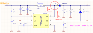
I got couple of LED drivers, driven from 4V Li battery. Most of them work well (output current 60mA is correct, wave is rectangular) but one has very erratic waveform with overshoots and output current does not go over 17mA)

Even the changing of IC and inductor and output diode does not change anything. Inductor goes very hot, normally its only slightly warm.

I have checked the PCB million times. Could there be some inherent design instability ? I have tested other supplies with input voltage 3.3-4.2 and different loads (22 to 30V LED strings)

It must be something obvious. Looks like the IC output does not turn on correctly ?

Please help :)
  • Hi Madis,

    Will adjust the output capacitance or SW inductance have any improvement?

    BR

    Patrick

  • I have not yet tried that.. but the values are checked with LCR meter and all are as calculated. Also, we have changed the components, so there are probably variations within component tolerance (10-20%) but no positive effect..

    What we did found out just now - our PWM freq was bit low, about 6.3kHz. Programmer changed it to 10kHz and everything started working... but then again he also cleaned the PCB and re-soldered diode and inductor. But this he had done before also (changing components) and that did not have any effect.

    I suspect its a chip problem, turn-on of MOSFET seems erratic.

    But we keep testing and also, if you got any more suggestions or ideas, please share ! :)

  • Also, I measured the shunt resistor with INSULATED high freq low impedance (2k) probe. Found no peaks there.

  • Hi Madis,

    Do you mean the IC works normally with 10kHz PWM?

    BR

    Patrick

  • Yes, the board which was malfunctioning, works now well with 10kHz.

    But.. reducing the PWM to "bad" frequency does not to seem to reproduce the error.

    Maybe it was a random soldering error, but I cannot imagine what wrong connection can cause such waveform.

    What I'm afraid most is that maybe there's some inherent instability ? Although, all the components are calculated, checked and doublechecked and waveforms look correct.

  • Hi Madis,

    So have you checked the source which generates the PWM? Is it stable?

    Since you have re-soldered some components, so have you also re-soldered the "erratic" IC? 

    BR

    Patrick

  • Yes, the source is stable. Actually - its not very frequency stable, as the MCU has only RC for clock. And maybe, in some circumstances, the PWM clock drifts below 4kHz.

    Also, before increasing PWM frequency we changed switcher IC TWO TIMES with no effect. Also we changed inductor, diode, capacitors and resistors :)

  • Hi Madis,

    OK, maybe next time you could also capture the waveform of PWM, to see whether this issue is really related to the unstable PWM.

    BR

    Patrick