This thread has been locked.

If you have a related question, please click the "Ask a related question" button in the top right corner. The newly created question will be automatically linked to this question.

TPSF12C1: VDD supplied to AEF

Guru 12050 points
Part Number: TPSF12C1
Other Parts Discussed in Thread: TPSF12C3

Tool/software:

Hi,

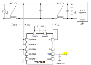
How is the VDD supplied to the AEF generated on the system? Generally, ACDC→DCDC (VDD=12V) is generated, so it seems that the filter does not work at startup. Does VDD require a power supply separate from the system power supply, such as a battery power supply?

Thanks,

Conor

  • Hi Conor,

    The bias supply for VDD must be chassis referenced just like the Y-capacitors shown in the drawing. Does the system have some kind of power up sequence before operation? If not, you will need a bias supply that is up during startup.

    Ben

  • Hi Conor,

    If there are no further questions, please click on the "resolved" tab to close the thread. Thank you,

    Ben

  • Hi Ben,

    In many cases, the power supply for the system is generated based on the ACDC. What kind of configuration is assumed for the bias power supply that is on at startup? There is no power-on sequence, but we are investigating use cases for using the TPSF12C1. Also, since these "bias supplies" are used on the primary side, they need to be Insulated, right?

    Thanks,

    Conor

  • Hi Conor,

    Usually, systems will have a power-on sequence to ensure proper voltages are set before initializing the system for operation. I am not sure what you meant by "what kind of bias supply configuration is assumed at startup" but usually there will be DC isolated voltage rail that is reference to the chassis.

    Also, since these "bias supplies" are used on the primary side, they need to be Insulated, right?

    Yes, the bias supply needed for the TPSF12Cx has to be isolated from the primary side and referenced to chassis GND.

    Ben

  • Hi Conor,

    If there are no further question, please close the thread by clicking on "resolved". Thank you!

    Ben

  • Hi Ben,

    Looking at the internal circuit of the TPSF12C1, it appears that the sensing input is three phases, but there is only one channel of output. Is there any information about the mechanism that can remove noise for three phases with only one channel of output?

    Thanks,

    Conor

  • Hi Conor,

    I am a bit confused with your question. The TPSF12C1 is designed for single phase applications. The TPSF12C3 is for three-phase applications. I hope I have answered your question.

    Ben

  • Hi Ben,

    Sorry, as per your comment. I was referring to TPSF12C3.

    Thanks,

    Conor

  • Hi Conor,

    I am still a bit confused with your question. Are you referring to an application where there is no neutral and there are three lines representing a single phase per line? Or are you asking if there is a setup where each IC minimizes the noise per phase?

    Ben

  • Hi Ben,

    It senses phases 1-3 and neutral, but the feedback only seems to go to the neutral line. How does it eliminate noise?

    Thanks,

    Conor

  • Hi Conor,

    The injected signal can be injected back to any of the power line input or in the neutral line. The reason for this is because the X-caps are much higher in capacitance (uF vs nF) than the Y-caps and because the of their higher capacitance value, the X-caps appear to be a short at the frequency of interest. Therefore, the X-caps "trans-communicate" the EMI noise canceling signal through the X-caps to each of the power line and to neutral.

    Ben

  • Hi Conor,

    Please let me know if there are any additional questions. Thanks,

    Ben

  • Hi Ben,

    I don't quite understand the point that "X capacitor appears to be shorted at the target frequency."
    Could you please explain in more detail?

    Thanks,

    Conor

  • Hi Conor,

    The impedance of a capacitor can be calculated by using the formula below:

    The frequency of interest is 150kHz to 3MHz and the X-capacitor value used is in the uF range, the impedance of the X-capacitor will appear to be small which we commonly say it is a "short".

    For example, if the frequency is 150kHz and the X-capacitor capacitance is 2.2uF, the impedance is around ~0.5ohms. 

    Ben

  • Hi Conor,

    Are there any other questions? If not, please click on "resolved" to close the thread again. Thank you,

    Ben

  • Hi Ben,

    By using AEF, the choke coil can be made smaller. However, are there any disadvantages to making the choke coil smaller, such as making it more susceptible to external noise? We plan to verify what changes will occur by installing AEF on the current filter, but if there is any information available at this time, please let us know.

    Thanks,

    Conor

  • Hi Conor,

    Unfortunately, yes, as the choke coil reduces in inductance so too does the differential mode inductance reduces in value.

    Ben

  • Hi Ben,

    I would like to know how to use TPSF12C1AEF design tool excel. I'm not sure how to enter parameters for Step.2: CM Choke in Excel. Is there a document that explains what values ​​should be inserted?

    Thanks,

    Conor

  • Hi Conor, 

    You will need to have a vector network analyzer (VNA) to measure the impedance of the chokes over frequency.  Here is an example of a VNA:

    https://us-shop.omicron-lab.com/products/bode-100

    When using the VNA, you want to obtain the magnitude of the impedance and phase.

    Ben