This thread has been locked.

If you have a related question, please click the "Ask a related question" button in the top right corner. The newly created question will be automatically linked to this question.

UCC28180: Ucc28180_AVG cadence simulation_ Gate Signal issues

Part Number: UCC28180
Other Parts Discussed in Thread: UCC28019, PMP22606

Tool/software:

Hello Everyone,

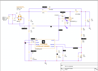
 Here i made a circuit to activate the Gate signal from UCC28180_AVG. But my gate signal amplitude was around 0.8mV only coming.

I'm not getting my gate signal properly. So, guys help me how to get gate signal. 

Here, i attached my schematic diagram  & O/p waveform also.

  • Hello Suriya, 

    The UCC28180 average model that you show must be used together with a "BOOSTCCMDCM" subcircuit to provide PFC simulation.
    The GATE pin on the model you show does not provide pulses.  Instead it provides a voltage that represents the duty cycle to be applied to the BOOSTCCMDCM subcircuit.

    Please refer to this earlier E2E thread on the same topic:  https://e2e.ti.com/support/tools/simulation-hardware-system-design-tools-group/sim-hw-system-design/f/simulation-hardware-system-design-tools-forum/784715/tina-spice-ucc28180-tina-spice-ucc28180-pfc?tisearch=e2e-sitesearch&keymatch=ucc28180%25252525252520simulation#

    TI does not have a true transient model of the UCC28180 controller which can show gate pulses.  Even though the UCC28180 product page lists two models as "...Transient...", they are both actually derived from the same average model internally.   

    Regards,
    Ulrich

  • Hello, Mr. Ulrich Goerke (@TI_Mastermind)

    I'm happy for your reply sir. For following your tips, i'm getting boosted voltage (Vout) by using UCC28180 and BOOSTCCMDCM subcircuit. This things i agree sir.

    Ucc28180 and Ucc28019 both spice model i'm using with Boost converter and the output was boosted voltgae.

    But my aim was i want to simulate the GATE Signal and i need to explain this things to customer's. Without knowing about GATE signal, how i explain to them.

    Or you suggest me to  any PFC CCM IC for simulation (with spice model) and on board oriented purpose. My need was i'm able to view the GATE signal properly.

    Or help me, how recreate that BOOSTCCMDCM subcircuit into actual components circuit diagram and also much more important is gate signal.

    Here, i'm attached schematic and output waveform. Check these, if any mistakes are available on schematic make me to correct that or give the better solution for this thing sir.

    Schematic:

    O/P: 

    Regards,

     Suriya

  • Hello Suriya, 

    Both the UCC28180 model and the BOOSTCCMDCM model are mainly a set of equations.  The UCC28180 model implements the M1, M2 and M3 equations found in the datasheet, and determines a duty cycle voltage.  Your simulation indicates that Dmax = 0.985.  The BOOSTCCMDCM model uses a different set of equations to translate the duty cycle voltage at GATE into an average current into the output diode. 

    It may be possible to design a new block to translate the GATE voltage into actual PWM gate pulses, on this premise: 

    Construct a fixed-frequency oscillator (probably best made using discrete ideal components) such that it produces pulses at the frequency of your choice, and the pulse width is linearly modulated from 0 to 98.5% by the GATE voltage (from 0V to 0.985V).  These gate pulses can then be buffered (if necessary) up to 10V amplitude to drive the MOSFET at D10, R14.   

    I think that might work.

    Regards,
    Ulrich

  • Hello Goerke

    Thanks for Reply.

    I'm trying to make voltage to PWM converter but i'm not getting the right component.

    Even the o/p volt was 0.9V, some IC's minimum voltage was 1V.

    Can you give suggest any part name to a  circuit and simulate the Gate signal.

    Regards,

     Suriya

  • Suriya,

    Please refer to PMP22606 to check if your design is correct.

    Thanks

  • Hello Suriya, 

    In my reply 27 days ago, I suggested for you to use ideal components to construct the V-to-PWM converter.
    (Sawtooth oscillator, ideal comparator, ideal op-amp, etc.)
    That way you do not have to worry about the limitations of commercial components.   

    Regards,
    Ulrich