This thread has been locked.

If you have a related question, please click the "Ask a related question" button in the top right corner. The newly created question will be automatically linked to this question.

UC3846: Parallel protector for BMS battery charging.

Part Number: UC3846

Tool/software:

Dear TI team,

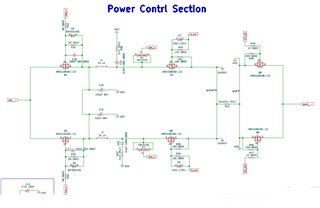
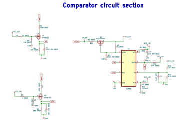
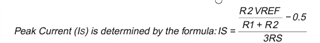
I have used UC3846 IC for current controlled PWM in my parallel protector for BMS battery charging. Instead of giving an controlled current of 2.2A it is giving 3-3.5A when switching of a_out b_out is measured. Please do help me with that.  
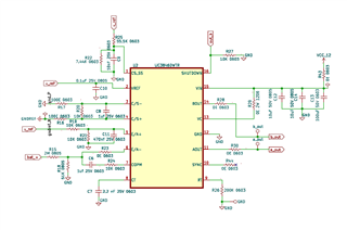
Also I am attaching my schematic for your reference.

  • Hi,

    Where is 2.2A you want to have? Where is 3-3.5A you see?

  • 3-3.5A is the output of battery while charging. I measured it through current clamp meter at negative side of battery and also through our BMS application which shows discharge current. Also i changed fosc to be 10KHz but it is showing 5KHz in a_out and 5KHz in b_out and discharge current is not changing even after changing fosc from 5 KHz to 10 KHz.

  • Hi,

    It looks your circuit you provided not include the 3 - 3.5A portion. Please provide the circuit showing that or indicate where is that current in your provided circuit. I am not able to know where that current is based on your word description.

  • Hello,

    Is it possible we can connect on zoom call or anything and discuss it so that we get to the solution faster.

  • Hi,

    You can just provide your circuit and use arrows or reference designators to show where the current is in your circuit so I can know clearly. This is a simple illustration and no need to use zoom call - why you cannot show the circuit flowing 3-3.5A current?

  • Hello,

    I am asking to connect on call because it can help us get to the solution faster. Ofcourse I can show you the circuit, let me draw a flow diagram of parallel BMS and show it to you what issue we are facing.

  • Hi,

    Show your current location first so I can see what you are looking at. Not sure why not just show the current location in your circuit? 

  • I am attaching picture of my schematic for your reference 

    Also i have changed the Rt Ct values to 100k and 2.2nF respectively in order to get Fsw 10KHz but a_out is showing 5KHz and b_out is showing 5KHz. As you can see at pin number 1 the divider R1 is 55.5K and R2 is 7.44K which givwes current limit to be 3.428A, i have also changed it to R1 = 47K and R2 = 6.04K which sets current limit to be 2.692A but still it is functioning with 3.5A only and I am not getting my desired results. To se the current limit I have manipulated R1 & R2 values using equation provided in datasheet which is attached below.


  • Hi,

    The current limit is peak not an average. You need to capture the voltage waveform across R42 then calculate the current to check if the peak is 3.428A or 2.692A, and how much difference. It looks you think the current limit is average but it is not. The limit is the peak current sensed on R42 peak voltage.

    The frequency based on RT and CT is oscillator frequency fosc. Section 7.2 diagram shows that fosc is split into half for each driver output so what you see fosc = 10kHz, and each driver 5kHz. this is correct.