This thread has been locked.

If you have a related question, please click the "Ask a related question" button in the top right corner. The newly created question will be automatically linked to this question.

BQ25672EVM: Testing Guide

Part Number: BQ25672EVM
Other Parts Discussed in Thread: BQ25672, TI-CHARGER-GUI, BQ25798

Tool/software:

Hello,

I am using the BQ25672EVM and have a question regarding the test setup. 

In the EVM documentation, a battery simulator is recommended to be connected to the BAT pin of the charger IC. However, I don't have a battery simulator or DC load available. Can I connect a discharged battery pack from my lab instead, and would it work?

Here's what I've done so far:

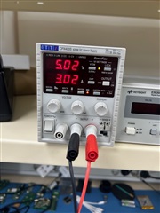
1. Connected PS1 (5V @ 3A) to the J1 connector.

2. Connected the battery pack to the J5 connector.

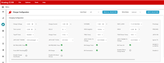
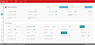
3. Launched the TI-CHARGER-GUI software and selected BQ25672 as mentioned in the initial EVM documentation.

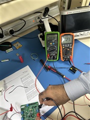
4. At step #4, when I turn on PS1 and connect the battery pack as load 1, I am unable to measure 8.55V at VSYS on the J3 connector. Instead, I measure 7.61V.

Could you please guide me on what might be missing in this setup that is preventing the correct voltage measurement?

  • Hi Ahmer,

    A discharged pack is okay.  If the PROG pin is set for 2S and the host has not written to the I2C registers to change SYSMIN, CELLS or BATREG bits, SYSMIN should be around 7.61V.  The user's guide needs to be updated to say that 8.55v applies only if the battery is fully charged.

    Regards,

    Jeff

  • Hi Jeff,

    Thanks for your response. I am writing the scenarios we tested for your understanding.

    1 Cell:

    We configure the charging profile for one cell through the TI GUI, and charging occurs in Fast mode for one cell. We set VSYSMIN to 5V through the GUI, and it outputs 5V on the EVM. However, as soon as we enable cell charging, VSYSMIN changes to the cell voltage. Please guide.


    2 Cells:

    When we configure 2S and set BATT voltage to 8.4V in the TI GUI and write the register, these values do not set on the EVM. The cells do not charge, and there is no current flow. However, the GUI displays fast charge in the status charge register. When we measure the charger voltage on the BATT connector, only the cell voltage appears, and the same voltage appears on VSYSMIN. In other words, the TI Charger GUI is not updating the profile on the EVM for the 2 Cells or 3 Cells.

    I am also attaching some screenshots of the test setup and the TI Charger GUI for reference. If we are misconfiguring any parameter in the GUI, please guide us. Your support would really help us. I have already integrated this charger IC into my product, but I first want to test this charger IC on the EVM. With good results and reference, I will move forward to test the charger IC on my product’s PCB.

    .

     Power Supply UsedTest SetupMeasurement for 2SQuick Start

  • Hi Ahmer,

    For 1 cell, setting SYSMIN above BATREG is not supported. SYSMIN is meant to be the minimum system voltage provided at SYS when battery is discharged.  Then SYS follows the battery up to BATREG, i.e. 4.2V for 1 cell.

    When using the GUI, you must disable the WD timer. Otherwise, the charger resets any I2C writes to default after the WD timer expires.  Also, when writing to the registers to change the cell count, the CELLS bit must be written first and then SYSMIN and BATREG.

    Regards,

    Jeff

  • Hi Jeff,

    We already tried this: "When using the GUI, you must disable the WD timer. Otherwise, the charger resets any I2C writes to default after the WD timer expires.  Also, when writing to the registers to change the cell count, the CELLS bit must be written first and then SYSMIN and BATREG."

    This did not solve my problem.

    I would like your detailed attention to this issue, which has blocked us from further testing of the EVM.

    Regards,

    Ahmer

  • HI Ahmer,

    Current meters in series with battery or simulated battery are not recommended.  If you short out that meter, does the charger work as expected?

    Regards,

    Jeff

  • Hi Jeff,

    I removed the series current meter but the results are same, charger is not working for 2 or more cells.

    Regards,

    Ahmer

  • Hi Jeff, 

    Waiting for you response !

    Regards, 

    Ahmer

  • Hi Ahmer,

    Can you turn on the ADC, do a read all and post the ADC values?  Using an oscilloscope, can you confirm whether SW1 or SW2 is/are pulsing?

    Regards,

    Jeff

  • Hi Ahmer,

    Wait!  You are using BQ25672 which is a buck only charger, meaning the input voltage at VBUS must be higher than the battery voltage.  If you need to boost and buck, I recommend moving to pin2pin and reg2reg BQ25798.

    Regards,

    Jeff

  • Hi Jeff,

    I understand now; this was the actual problem. However, it was not clearly mentioned in the EVM user guide that the input voltage at VBUS needs to be increased for two or more cells.

    Thanks for your insight.

    One last thing, can you please confirm if BQ25798 and BQ25672 are drop-in replacements for each other?

    Regards.

    Ahmer

  • Hi Ahmer,

    Yes, BQ25798 and BQ25672 are drop in replacements.

    Regards,

    Jeff