This thread has been locked.

If you have a related question, please click the "Ask a related question" button in the top right corner. The newly created question will be automatically linked to this question.

TPS1641: Sometimes shorted when connecting power

Part Number: TPS1641

Tool/software:

Hi,

We assembled some 10 samples of our new PCB that uses the TPS16416 as protection device.

We had two cases:

1. While a colleague was making some tests heard and saw a spark when plugging the PCB to a bench power source and everyone assumed that he did something wrong as there were many cables around.

2. Today (one week later) another colleague was testing a new firmware, while having everything disconnected to the PCB, from a different bench power supply set at 20VDC output and limited to 200mA maximum output: first connected GND to the PCB and before he could even touch the VCC connector of the PCB with the power connector a spark could be seen between.

In both previous cases the result is the same: the TPS16416 is shorted and there is no output, we tried disconnecting the PCB and connecting it to power, also waiting for all capacitors to be discharged but not luck in any of the cases. After that, in one of the PCBs, we tried bypassing the TPS16416 input and output to see an small spark above the TPS16416 and some smoke.

IN both previous cases the solution is the same: removing the TPS16416 from the PCB and shorting the input with the output. Everything works great without the TPS16416.

As we dont know what could be causing this we would like to ask your advice/opinion about this. We have made many tests everyday and we have plugged/unplugged many times the PCBs but only two times we saw this issue. 

  • Today it happened the same to a third PCB, this time the colleague was connecting the PCB to 30V input and again he saw and heard the spark when he touch the VCC pin of the PCB with the power bench connector.

    This time we tried measuring the voltage at different pins:

    - FLT measured 0V

    - OVP measured 0V

  • Hello Francisco,

    Do you have any waveforms while this fault happened?

    Can you try with TPS16412 which is same pin to pin and size and it has IN to OUT short detection?

    Since you mentioned no other fault happened. So, I am suspecting it could be IN to OUT short.

    Thanks 

    Amrit 

  • Hi Amrit,

    No, there are no waveforms, I can just offer you the settings of the power bench, where we modify the voltage and keep the output limited in a range between 200mA and 150mA.

    We could order samples of the TPS16412 and use it to replace the originally assembled TPS16416

    Could you tell me why a IN to OUT short would appear? We havent experienced any issues on the PCBs where we have removed the TPS16416

    We didnt choose the TPS16412 as the e-fuse is used in the main power supply of the PCB, therefore if the TPS1641X has no output, there is no MCU that can detect the FLT output low to change EN/SHDN input.

  • Hello Francisco,

    TPS16412 will not be a good option since you are using buck DC/DC at output.

    Since the device is failing sometimes. I am suspecting it could be because of voltage spike (Ldi/dt) because of stray inductance present in long trace PCB or the long supply wire which you could be using.

    To sustain the voltage spike, you can use TVS diode and more capacitors at input side. 

    Thanks,

    Amrit  

  • We are already using a 33V bidirectional TVS, filter and capacitors to handle voltage spikes.

    We havent experienced this issue with the spark until we included the TPS1641 in our design. Yesterday you proposed me to use a TPS16412 and we already purchased the samples.

    Today you say that this is not a suitable device if we using a buck DC/DC at output. Based on what? Why? Do you have an alternative proposal to the TPS1641X?

    Please get your answers right and discuss it with a colleague in case you have doubts, you cant go around giving random answers to companies that come here looking for TI support and assemble thousands of TI parts every year.

    Thanks

  • Hello Francisco,

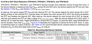
    Snapshot from datasheet. Please refer to the table above about the switching load freq and current ripple. If your load falls under this, you can use TPS16412.

    I have overlooked the DC-DC converter load in schematics earlier. Apologies

    We value about customers and will continue to help with your applications.

    Can you fill in your system requirement in below design calculator and send. If possible, share your extended schematics (input side) and PCB for review.

    TPS1641-CALC Calculation tool | TI.com

    Thank You

    Amrit 

  • Hello Amrit,

    If you had a private discussion line we would be able to share further details and schematics but since you only have public forums we have limited information we can share with you.

    Our DC/DC switching frequency (fsw) is set to 500kHz and ripple load current varies depending on the input voltage which varies from 60mA (lower input voltage) to 180mA (higher input voltage).

    We have observed that all of the issues, when we saw the spark and the TPS16416 got damaged (yesterday happened to myself), always happened when the bench power source was connected to a voltage between 20V and 30V. We also often test the PCB between 10V and 14V and in that voltage range no one had issues.

    Checking carefully your screenshot, we can notice that the TPS16416 should be able to be used in all cases.

    Check the calculator screenshot. Please note that our current design is the one showed in first message as we modified the resistors of the voltage divider to match the values we prefered 

    I kindly ask you to push this case and get back to us faster, as waiting one day for every answer is delaying a lot our ability to fix this issue.

    Thank you

  • Hello Francsico,

    I sent you request to talk for personal chat.

    You can send your schematics there.

    you should also include the output caps for e-Fuse used in DC/DC converter input.

    Thanks

    Amrit