This thread has been locked.

If you have a related question, please click the "Ask a related question" button in the top right corner. The newly created question will be automatically linked to this question.

BQ24650: Hiccup problems

Part Number: BQ24650

Tool/software:

I am looking for help with a problem related to a PCBA with a BQ24650 charger for a 12V lead acid battery.

The used solar panel is a 3W 18V type, so the MPPT point is also set to 18V. When shortcircuited the panel delivers its rated current.

When I use a power supply at 19V with 1A current limiting, it pulls 1A current and PSU voltage drops to 18V like it's supposed to.

Now when I use the actual solar panel it seems to be stable at lower currents (<50mA) but starts to hiccup at anything higher. STAT1 led is blinking.

The solar panel voltage seems to be stable at 18V, or even seem to jump up a bit (indicating charger disconnection).

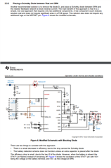
Here is the schematic:

And the associated layout: (4 layer, copper pour removed for visibility)

Some suspicions:

- Could it be due to charger termination setting somehow?

- Could it be due to the higher charge current? It's set to 2A in case a PSU is used, but solar panel is only 160mA max. Could this cause issues?

- I have put the resistor feedback network before the diode and compensated the forward voltage. Maybe this messes with the feedback loop?

- Something else?

Thanks in advance,
Jesse van der Zouw

  • Here is a video of the measured current going into the battery. As you can see it starts cutting off randomly

  • Seems to perform stable now that I bridged the output diode. Maybe this interferes too much with the feedback loop, thus the charger thinks the battery is absent. Could there be a way to fix this without PCB modification? Maybe extra caps across the solar panel? Or extra caps across the battery?

  • Hello Jesse,

    Seems to perform stable now that I bridged the output diode. Maybe this interferes too much with the feedback loop, thus the charger thinks the battery is absent. Could there be a way to fix this without PCB modification? Maybe extra caps across the solar panel? Or extra caps across the battery?

    Heres a appnote similar to your setup: https://www.ti.com/lit/an/slva829/slva829

    We recommend placing the diode inbetween the SRN pin and the resistor feedback network, and adding an extra capacitor(10uF) after the diode.

    It might be possible to resolve this issue by placing 10uF after diode, but I can not guarantee this will work.

    Best Regards,

    Christian.

  • Okay this requires a PCBA cut and patch, but should be possible.
    Or I will just bridge the diode and accept having no reverse polarity protection if really needed.

    I just tested the reverse polarity protection with my current configuration, and it does not seem to work, Q2 is heating up.
    Does this have something to do with removing D1? Why would one need to remove this?

  • Hello Jesse,

    I just tested the reverse polarity protection with my current configuration, and it does not seem to work, Q2 is heating up.
    Does this have something to do with removing D1? Why would one need to remove this?

    The BQ24650 is a legacy device so I can only go off the limited information that we have. The appnote states that the input diode needs to be removed. We do not have any information on why the input diode has to be removed. 

    Do you see any improvement if you keep D1 and add the capacitor after the output diode?

    Best Regards,

    Christian

  • Yes, with the diode in place and the feedback resistors and a bulk cap after the diode (instead of before) it works. However, it does not provide reverse polarity protection , Q2 starts heating up. This is also not what is claimed in slva829, as there it's used to prevent leakage current, but I would think a schottky diode on the output would provide protection against a battery being attached with wrong polarity. Am I mistaken?

  • Hello Jesse,

    I'm reviewing this information, and will provide you an update after I gather more information.

    Best Regards,

    Christian

  • Hello Jesse,

    Please refer to this app note for further inormation on reverse polarity protection:https://www.ti.com/lit/an/slva139/slva139

    According to the appnote, your output diode is backwards. However if you flip the diode, it could prevent the battery from charging. It may be a better idea to have a MOSFET instead of a diode.

    Best Regards,

    Christian.

  • Hello Christian, okay I understand, thanks for your help.