This thread has been locked.

If you have a related question, please click the "Ask a related question" button in the top right corner. The newly created question will be automatically linked to this question.

UC3842: During start-up, the output pin has a 0-level output

Part Number: UC3842

Tool/software:


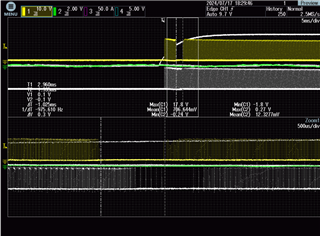
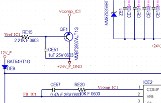
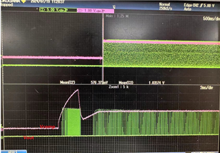
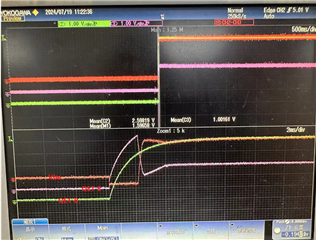
The yellow waveform is the pin6 output waveform, and there is a 0 level of 1ms during the startup process.During the output 0 level time, the level of the 1 pin drops to 0.7V, which may be related to comp

I want to know why is this happening,and whether it will have an impact on the circuit and the use of the chip

  • The cause is likely coming from the circuits connected to COMP. It seems you are trying to add external soft-start which is fine to do but check the QE1 Vbe and make sure the transition is smooth, especially during startup with IC=0V on CE51. Also add a Schottky across RE15 with anode connected to QE1 base and cathode connected to "Vref IC1" . In addition, the loop response is very slow which means that if there is any over/undershoot on COMP, it will take long to recover. It could be that COMP is transitioning low during startup and the loop response is so slow, it allows the COMP to continue low, reaching ~0V until it finally recovers positive...this seems to be taking about 1ms. Look at the time constant of CE57 and RE20...DC regulation will not be good and the transient response will be slow.

    Steve

  • Dear Steven,

            I retested two graphs and also add a Schottky across RE15,adding diodes doesn't change much.

    ...

  • Next I would recommend to measure the closed loop response. I'm guessing the BW is low and the slow response is allowing the COMP signal to dip to a level that is shutting off OUT for ~1ms. Also, check the converter output of whatever the topology is? Also, you can use TI Power Stage Designer to sim your power stage and help model/optimize your control loop.

    Steve

  • Thankyou Steven,and I still have some doubts," the closed loop response"and the BW--refers to the rise time of the output voltage?“check the converter output of whatever the topology is?” ---I didn't quite understand.

  • If you want to optimize the transient/start-up response, you need to know what your closed loop frequency response is doing. You need to measure the control-to-output closed lop response using a network analyzer to obtain what is more commonly referred to as the Bode Plot which displays the gain and phase response vs frequency.

    What I meant by “check the converter output of whatever the topology is?” is simply to ask, what is the converter output doing relative to the OUT missing pulses? It could be that the converter output load is such that it is commanding zero duty cycle (light load operation). Is the output start-up showing controlled soft start? If there any under/over-shoot in the startup waveform?

    Steve

  • The output voltage is a little overshooted, and when the pulse is zero, the voltage drops and then remains flat.I'm going to learn about frequency response.

    Thank you very much for your replyGrin