This thread has been locked.

If you have a related question, please click the "Ask a related question" button in the top right corner. The newly created question will be automatically linked to this question.

TPS65987DDK: Schematic review

Part Number: TPS65987DDK
Other Parts Discussed in Thread: TPS65987, TUSB1064

Tool/software:

Hello,

My name is Pavel Skoda.

I received great support from David and Tommy for my HUB design in the past.

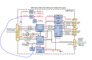
The last recommendation from Tommy was to implement to my schematic the TPS65987DDK PD controller.

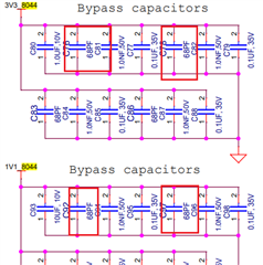
I finished my schematic and I would like to ask you if you could please review it and send me your feedback. I posted my questions on the page4 of the schematic.

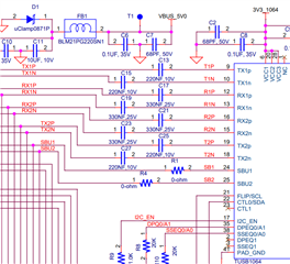
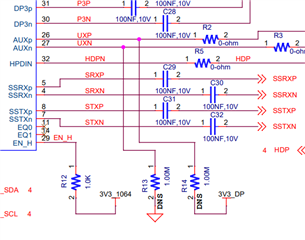
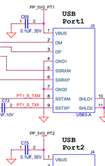
I am including the pdf of the schematic, please review it and provide your feedback.

Thank you very much!

Pavel Skoda

SCH_255-00204-00_REV1_3X USB HUB(used5-notes).pdf

  • Hi Pavel,

    I mainly support the USB-C products, so will provide feedback on the TPS65987 portion. I will redirect the thread to the team that supports the TUSB parts so that they can also provide feedback.

    • LDO1V8 has a max capacitance of 6uF. You currently have a 10uF cap, we recommend a 4.7uF.
    • If PPHV2 is unused, ground those pins
    • This will depend on the power configuration somewhat, but I recommend using the BP_NoWait dead battery configuration for your ADCIN1 divider. This is the one typically used with the SPI flash. This could be the .6 - 1 div setting
    • HRESET abs max is LDO3.3 + .3. Tying to VBUS_5v0 will damage the part. Recommend attaching to a 3.3V bus.

    Questions:

    U6 connections & Power:

    - mostly good, see comments on VBUS_5V0

    What is the purpose of the Flash memory U7. Can I remove it?

    - On boot, the PD controller needs to load a fw and configuration image from an external memory. U7 serves this purpose. The image contains, patches, bug fixes, and configuration information specific to your system. You can configure and generate the image using the GUI tool found on the product page. You need to load the image on boot, so you can not remove it.

    Is it OK to short the SPI lines?

    - because of the previous comment, no

    Is power "VBUS_5v0" connection from Host to U6 correct?

    The VBUS on PD controller to Type-C connector connections are fine.

    You have 3 buck converters taking power directly off of VBUS (U16,17,18). This is not recommended. You should be connecting VIN of those ICs to the PPHV_5V0 bus instead. There is also a limit of 10uF on the entire VBUS node.

    Typically power will not be taken directly off of VBUS, and will be drawn from the system side(PPHV)

    Is it ok to use PPHV5V0 as the power output and leave pins 1 and 2 floating?

    Yes, within the GUI, you will need to configure the part to use the PPHV1 path and not the PPHV2 path.

    Thanks and Regards,

    Chris

  • Hi Pavel,

    Here are my comments on the TUSB1064:

    1. If you want to pass 8kV ESD testing, I recommend adding 2 ohm series resistors on the TX/RX lines between the 1064 and the type-C connector

    2. Add 2Mohm pulldowns on SBU1 and SBU2 between the 1064 and the USB-C connector per the datasheet recommendation:

    3. Populate the 1M pulldown on AUXn and the 1M pullup on AUXp.

    I'll let my colleague review the hub in your schematic.

    Best,

    Shane

  • Hi Chris,

    Thank you so much for your review and also forwarding the schematic to other team for review. I will make all suggested changes in the schematic.

    I have one more question:

    Would you recommend using the PPHV2 path instead of the PPHV1 path (so I do not have to use GUI for path configuration)? Please, let me know if this would be better way to use the power VUSB_5V0 on input pins 3,4,13,14.

    Thank you once again for great help.

    Pavel

  • Hi Shane,

    Thank you very much for your time reviewing my schematic!

    I will implement all recommended changes that you provided (and yes, I will need to pass 8kV ESD testing).

    Thank you so much forwarding the HUB portion of the schematic to your colleague - I am looking forward to see the results of that review as well.

    Thank you very much for all your help.

    Pavel

  • Hi  Pavel:

        I'm working on Hub  portion review, will send review result  before Mon.

    Best

    Brian

  • Hi  Pavel::

          Hub schematic looks good.

         for the cap on downstream port  Vbus, it  should be >22uf.

    also replace decoupling caps 68pf with 0.01uf on 1.1v and 3.3v

    Regards

    Brian

  • Hi Brian,

    Thank you so much for reviewing the HUB schematic.

    My big appreciation!

    Pavel

  • Hi Chris,

    The way I am using power on the U6(TPS65987DDK) - Do you think it would be better to use the PPHV2 path (instead of PPHV1) for my PPHV5V0 output and short pins 11&12 to GND instead of 1&2?

    Please let me know.

    Thank you a lot.

    Pavel

  • Pavel:

       Chris  may not see this ticket, can you submit another ticket just for PD controller?

    Regards

    brian