


Tool/software:
Hi team,
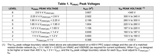
When designing with AC170~264Vin, 750Vout, according to the notes in Table 1, kr = 3V/750V = 0.0004.
If the VIN peak voltage is 240Vpeak (170Vac), Vvinac is 0.096V, so should I use 0.398 for kvff?
Tool/software:
Hi team,
When designing with AC170~264Vin, 750Vout, according to the notes in Table 1, kr = 3V/750V = 0.0004.
If the VIN peak voltage is 240Vpeak (170Vac), Vvinac is 0.096V, so should I use 0.398 for kvff?
