


Tool/software:
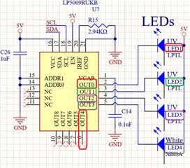
Our four LED board (photo, below) is configured as follows:
- LED 1 (UV): OUT_0
- LED 2 (UV): OUT_1
- LED 3 (UV): OUT_2
- LED 4 (White): OUT_3

Each LED shall display independently in sequence.
These initialization commands are sent via I2C (register / value):
- 0x00 / 0x40
- 0x02 / 0x00
- 0x07 / 0xFF
- 0x08 / 0xFF
- 0x0B / 0x00
- 0x0C / 0x00
- 0x0D / 0x00
- 0x0E / 0x00
The OUT_3 command (below) successfully turns ON the WHITE LED 4 individually (photo of WHITE LED 4 ON with UV shield, below).
- 0x0E / 0xFF

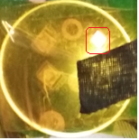
After successfully commanding OUT_3 OFF (WHITE LED 4 OFF, below), all lights display OFF. Next, the OUT_2 command (below) successfully turns ON the UV LED 3 (photos with UV shield, below; first photo, UV LED ON; second photo, UV LED ON masked with tape).
HOWEVER, in error, the WHITE LED 4 also turns ON simultaneously (marked in photos, below; displays RED / PINK? tint).
- 0x0E / 0x00
- 0x0D / 0xFF

Thank you for insight into why the independent control commands do not produce the expected results (i.e., turn ON UV LED 3 independently).
Karol S. Schulewitz


 :
:
