This thread has been locked.

If you have a related question, please click the "Ask a related question" button in the top right corner. The newly created question will be automatically linked to this question.

TPS62873-Q1: Power IC Compensation RC selection for Phase margin

Part Number: TPS62873-Q1
Other Parts Discussed in Thread: TPS62873

Tool/software:

Hi TI,

I want to know how to select compensation R,C of TPS62873Y1.

These are Ti's Guide about comp R, C

  AP EVM PWR EVM Datasheet
Rz 1.8k Ohm 2.43k Ohm 2.4k Ohm
Cc 3.3nF 1.8nF 0.82nF
Cc2 10pF 10pF 10pF

(we used TDA4VE)

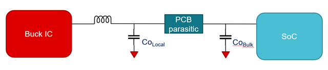
I checked and followed TPS62873 Datasheet and I think the key parameter is output capacitance.

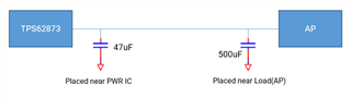
If designed below sch. which ouput capacitance should we use for compensation's parameter?

 1) 47uF - Only capacitor for PWR IC

 2) 547uF - added Load's capacitor

Best regards,

  • Hi Jihoon,

    Thanks for reaching out to us.

    The TPS6273-Q1 datasheet (Sec 10.2.2) provides a detailed design procedure on calculating the required passive components (Lout, Cout) including the compensation values. The load transient specs need to be clear before using the calculation formula.

    On the other hand, the total output capacitance (near PWR IC + near load or SoC) needs to be considered in the calculation of compensation network (Rz, Cc, Cc2). You can also validate your design using the Simplis model (see link below). The PCB parasitic can be added in the simulation as well to have a more accurate result (see diagram below).

    I hope I was able to address your queries.


    Models: https://www.ti.com/product/TPS62873#design-tools-simulation

    Best regards,

    Excel