This thread has been locked.

If you have a related question, please click the "Ask a related question" button in the top right corner. The newly created question will be automatically linked to this question.

TPS63900: Fuse with high impedance making the IC not working properly

Part Number: TPS63900

Tool/software:

Hi,

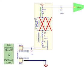
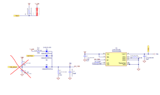
I encountered problems with the TPS63900 on our PCBs. I have a fuse of 15 Ohm mounted between the battery and the input of the IC. When I put a load on the output, I have huge voltage drop making the output first fixed at 3V useless, it's going down to 1.3V.

I also have the EVM module to test the IC to test current limitation and it kinda worked, but with bigger load it can't supply the 3V output.

I also made tests without fuse, and it worked correctly. And with another fuse with lower impedance, 8 Ohm, it worked better (with bigger load), but not completetly.

If you could help me understanding the behaviour of the TPS63900 I would be more than grateful. Thanks

  • Hi Leo,

    When a high impedance fuse applied, there will be a big voltage drop at this fuse.
    For device tps63900, it has uvlo_off detector which menas once input voltage is lower than 1.8V, device will shunt down. Then the voltage drop at fuse disappeared because no current goes through. Then input voltage of TPS63900 increased and device again. cycle by cycle.

    Regards

    Tao

  • Hi Tao,

    Thanks for your answer.

    I get the idea but I'm not sure this is why the TPS is not working properly. I measured the input current passing through the fuse and it's not more than 30mA. Which means the fuse is not creating more than 450mV of voltage drop (15Ohm * 0.03A). I'm supplying 3V in the input.

  • Hi  Leo,

    Measured with a multimeter? Mostly, the value you got with a multimeter is a RMS one, which means the peak current can be much higher.

    Regards

    Tao

  • Hi Tao,

    I measured with a scope for the tension, and with a Keithley for the current.

    For sure the fuse is creating the problem, because when I put a supercapacitor of 0.47F between the fuse and the input of the TPS, it works. Which means when the TPS have enough current to draw easily, it will start properly.

    But what's confusing me is that on paper, when you read the datasheet and measure tensions and current, the circuit should still work with the fuse. But in reality, the fuse is for sure 100% responsible of that trouble.

  • Hi  Leo,

    Yes, device work with a fuse should be fine. But once your impedance is too high, it will make device swiching from working and not working.Grinning

    Regards

    Tao

  • Ok so, can you please recommand me a DC/DC with similar characteristics but that can work with around 20 Ohm input ?

    Thanks

  • Hi  Leo,

    No DC-DC converter can work normally with this high impedance fuse.

    Regards

    Tao

  • Hi Tao,

    Ok I see, so can you help me chosing a capacitor to make the DC/DC have enough current to start and work normally ?

  • Hi Leo,

    I am afraid i am not able to do this, basic rule for cap selection is we should make sure valley of input voltage is higher than UVLO_off when load is maximum, better to have some margin.

    Regards

    Tao

  • Hi Tao,

    I'm not sure to fully understand what do you mean by valley of input voltage. If you could clarify I would be grateful.

    Currently the UVLO threshold is set at 1.75V

    And the maximum current consumption of my PCB is 70mA.

  • Hi  Leo,

    As you know, the input voltage of switching device mostly is not DC only, also has AC ripple. That means, there will be a peak and a valley value of input voltage. The actual valley voltage is depend on your system, such as your load type(constant or a pulsed one),  input impedance(fuse here), connection between your power supply and converter, etc.

    Yes, for this device, typ UVLO is 1.75V, but minimum value of this is 1.73. So, you should make sure the valley of input voltage is higher than 1.73V.

    Regards

    Tao