This thread has been locked.

If you have a related question, please click the "Ask a related question" button in the top right corner. The newly created question will be automatically linked to this question.

TPS2HB35-Q1: Extended power supply disable short circuit and Iout(standby) questions

Part Number: TPS2HB35-Q1
Other Parts Discussed in Thread: TPS1HTC30-Q1

Tool/software:

HI experts!

  1.  found a related question in below link that explains the short circuit is disabled when VBB > 18V .https://e2e.ti.com/support/power-management-group/power-management/f/power-management-forum/1308376/tps2hb35-q1-tps2hb35-q1-influenced-ec-spec-under-extended-supply-voltage
    1. VBB>18V cannot provide short-circuit protection. Does it mean that it cannot guarantee safe protection every time, or does it mean that this function is invalid and cannot be identified and triggered?
    2. If a short circuit or overcurrent occurs, can it still be reported using vsense?
  2. Regarding the Iout(standby) question. Figure 7 can not help because VOUT=0V but customer real condition isn't 0V but 4V
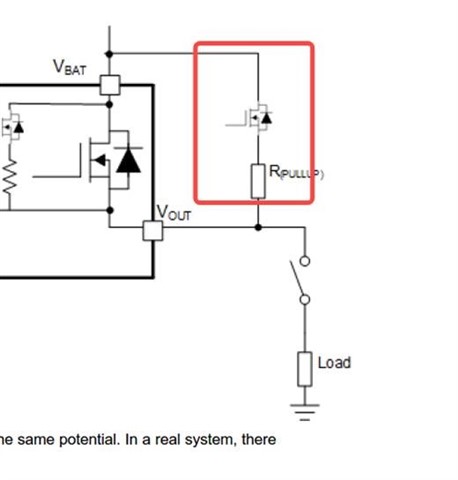
    1. Customer will use the high-side switch in Standby and DIAGNOSTIC modes. Mainly in DIAGNOSTIC mode, the main FET is not turned on, but the internal 1M diagnostic FET is turned on, and at this time, they have a diagnostic structure like the figure below, which causes the VOUT voltage to be pulled up (about 4V). At this time, they want to know the leakage current at the IOUT end. The temperature condition is -40°C to +125°C . And the voltage is 9~18V and 18V~28V for two conditions.


Thanks!

Josh Wei

  • Hello Josh, 

    When VBB > 18V (outside of nominal supply range) the device is not guaranteed to display proper operating functionality as expressed in the datasheet. Operation outside of the nominal range may cause physical damage to the device. As stated in the linked post, the device is built to be operated in 12V automative systems. 

    For more information about operating outside of the intended voltage range reference this FAQ: 

    [FAQ] What is TI High Side Switches' extended voltage range? - Power management forum - Power management - TI E2E support forums

    When DIA_EN is high the 1M resistor will act as a path to output in the system. The leakage is calculated by taking the 18V / 1M. In addition to this, when DIA_EN is high the leakage current will be the same but the current consumption in diagnostic mode increases (3mA) which will be added to that leakage value. 

    Thanks, 

    Alan

  • Hi Alan,

    Thanks for your reply. If the answer cannot be shown in public forum, please send to joshwei@ti.com.

    Please consider a transient working condition and short circuit happened. What action will this HSS operate, will it recognize the fault or not?

    If cannot guarantee to display proper function  when VCC>18V, how to secure safety in this range? Will be recognized by Vsns?

    Please help to full fill this list:

    Can not guarantee function when VBB>18V

    Description

    1
    2
    ...
    N

    Please help to answer:

    The leakage current at the IOUT end. VBB=28V,VOUT=4V,diagnosic mode and standby mode.

    1. Condition 1: Voltage is  9~18V. Temperature condition is -40°C to +125°C .
    2. Condition 2: Voltage is 18V~28V. Temperature condition is -40°C to +125°C .
  • A short-to-ground will cause the device will enter the FAULT state. This will be available on the SNS pin This case is explained in section 9.3.1 of the datasheet.

    Working outside of the recommended operating conditions is not supported for this device. This was rated to operate for 12V automotive applications. There are devices that can operate at higher voltage levels like the TPS1HTC30-Q1.

    Condition 1 Leakage:

                    Diagnostic Mode: (18V / 1M) + 3mA = 3.018mA

                    Standby Mode: 18V / 1M = 18uA

    Condition 2 Leakage:  

                    Diagnostic Mode: (28V / 1M) + 3mA = 3.028mA

                    Standby Mode: 28V / 1M = 28uA