This thread has been locked.

If you have a related question, please click the "Ask a related question" button in the top right corner. The newly created question will be automatically linked to this question.

BQ40Z80: Bad AFE readings

Part Number: BQ40Z80
Other Parts Discussed in Thread: BQSTUDIO

Tool/software:

Hi,

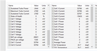
We are testing our first prototypes for a 4S2P pack using the BQ40Z80. The first two boards came up fine, but when I plugged into the third, I am getting strange readings. See picture below. All cell voltage read 0V, but BAT pin read 28V. (BTW - all voltages read with a multimeter at the pin inputs are correct, ~3.9V per cell). Also, cell currents reading 32A when there is no load connected. However TS1 and TS2 are reading correctly at about room temperature. It seems like the AFE is out of synch or something. Is there a way to reset it? I tried voltage calibration but this failed:

  • Hi Jamie,

    Does this problem consist if a power on reset is attempted on the part?

    Can you please confirm with a multimeter what is being passed across the sense resistor at this time as well?

    Regards,

    Anthony Baldino

  • Hi Anthony,

    Removing and reapplying power doesn't change the state. Also, there is no current flowing, so no voltage across the sense resistor. Does this mean the chip is dead?

    -Jamie

  • Hi Jamie,

    If possible, can you please confirm that there is a pulsing of rate 1s (or 4s if the device is in sleep mode) being seen from the TS1 pin through an oscilloscope? This will confirm if the device is in a functional state or not. Also, can you please share a screenshot of the entire bqStudio screen when the device is connected?

    Regards,

    Anthony Baldino

  • Hi Antony,

    I do see the pulse on TS1, but it is at 780msec intervals. Screenshot is below. Note that this is being powered off a supply at 11.6V with no cell voltages. However, when I had the cells connected on an actual battery pack, they still read 0V. The pack voltage here is being read at over 20V and cell currents are obviously way too high (only 10mA at the supply). We are thinking about just replacing the chip.

    -Jamie

  • Hi Jamie,

    I do see the pulse on TS1, but it is at 780msec intervals.

    This should be fine, it seems like the device is active and in normal mode.

    Note that this is being powered off a supply at 11.6V with no cell voltages. However, when I had the cells connected on an actual battery pack, they still read 0V.

    This should be fine for voltage and current evaluation since they do not rely on the values created by the learning cycle.

    The pack voltage here is being read at over 20V and cell currents are obviously way too high (only 10mA at the supply).

    Has there been any calibration done to the device that may skew the pack voltage reading to this level?

    We are thinking about just replacing the chip.

    As you stated before, the gauge is getting the proper cell voltage at each of the pins, so I believe that it might be a good idea to try swapping the part out for a new one and seeing if this is able to mitigate the issue. Regarding the current measurement, was there any difference in sense resistor being used or is it a 10mOhm resistor?

    Regards,

    Anthony Baldino