Because of the holidays, TI E2E™ design support forum responses will be delayed from Dec. 25 through Jan. 2. Thank you for your patience.

This thread has been locked.

If you have a related question, please click the "Ask a related question" button in the top right corner. The newly created question will be automatically linked to this question.

LM3488: How to correctly import and use LM3488 Pspice model on Orcad and simulate custom schematic?

Part Number: LM3488
Other Parts Discussed in Thread: LM5155

Tool/software:

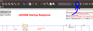
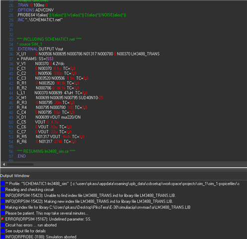
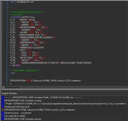
Hello, I am trying to simulate custom schematic of a LM3488 Boost converter. On device page there are two simulation files: encrypted and unencrypted. I downloaded Orcad free trial and watched some tutorials how to perform transient analysis. I am still very new to Orcad and only know the basic functions, but I managed to import .OPJ file of a encrypted version, and Inside there are two simulations prepared, but as I said, I need to create my custom schematic with different values and a bit different component placement. I tried using model of this file on my simulation project and I got error after running simulation: 
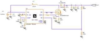
  Here is the schematic of my simulation project
I don't really know what is the problem, because I just added encrypted file library and inserted LM3488 component on my schematic. I tried using unencrypted file, but it only has .lib file, which I tried adding and then using a bit differently looking LM3488 symbol, but got same error.
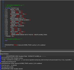
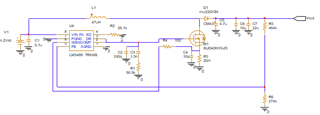
Can someone please help me and give a step by step tutorial how to import just a symbol of LM3488 file into OrCad and how to use it to simulate circuit that I showed above? Or maybe how to fix current error and simulate transients?

  • Hi Dominykas,

    Thanks for using the e2e forum and PSpice.

    The error indicates that the simulator cannot find the LM3488 library file.
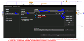
    You can allocate the library file manually by following these steps:

    1. Click on "Edit Simulation Profile"

    2. Go to Configuration Files --> Library


    3. Browse for the lm3488_trans.lib file and click on "Add to Design"
    The LM3488 model should then be found by the simulator.

    Please let me know if you need additional help.

    Best regards,
    Niklas

  • okay, adding .lib file seems to solve that problem, but now I get error, that SS is not defined:   Is it even possible to use my chips model for custom designs ? Because as I understand, it provides start-up and some other simulation, you can select it by setting SS to 0 or 1. Does it work like regular spice model ? Can I use it to simulate output voltage, current, power, calculate efficiency? Because my goal is to see how my circuit behaves on certain scenarios, loads and get output voltage, output current, efficiency coefficient, also output voltage ripple and compare them with different components. 
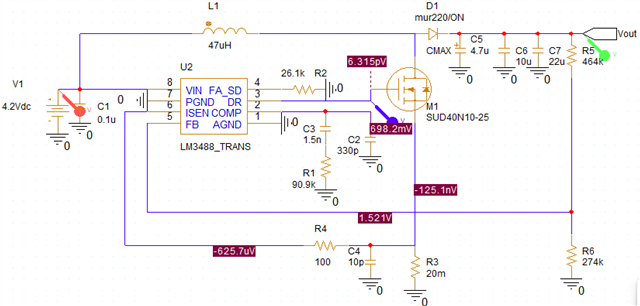
  • Okay, I manage to solve the problem, SS parameter was left empty, I had to set it to 1 (or 0). It seems to run simulation now, but I don't get the result I hoped, so maybe I will try to find some other way to optimise my design.

  • Hi Dominykas,

    Thanks for the update.
    You are correct, the SS value needs to be set to 0 or 1.
    I recommend setting it so 0, which means the device will start up with softstart just like the real device.
    Setting the value to 1 skips the sofstart, which can safe simulation time if only steady-state operation is relevant.

    If you are in the early stage of designing, I can also recommend switching from LM3488 to LM5155.
    LM5155 is more modern than LM3488, therefore has better features and newer simulation files, quickstart calculators and reference designs.
    https://www.ti.com/product/LM5155

    Please let me know if you have more questions on either of these devices.

    Best regards,
    Niklas

  • My project is in production phase and it uses LM3488 so using other converter is not an option, but currently it is required for me to get simulation file to further optimise the design. Is it possible to ask Texas instruments to make fully working Pspice model (or any other spice model, maybe for Kicad v8) with all features, so I could simulate it (my input voltage is 3.5-4.2 V and output should be 6-36 V), because current model does not seem to work properly, when I use my circuit (which is working fine in real and generating voltages from 6 to 36 V).  

  • Hi Dominykas,

    If you are already in production phase, the LM3488 is still a good product choice and can be used without concerns.

    The PSpice model for LM3488 is capable of simulating most of the device features, including overcurrent protection, overvoltage protection and undervoltage lockout.
    Some features as overtemperature protection cannot be simulated with this model and this will also not be implemented in the future.

    We should be able to get usable simulation data for the given specs with the existing model, so we may need to look deeper into the setup.
    Looking at your simulation schematic, it looks like the DR and COMP traces are placed on top of each other. Can you make sure the schematic is properly routed and re-run the simulation?
    Thanks and best regards,
    Niklas

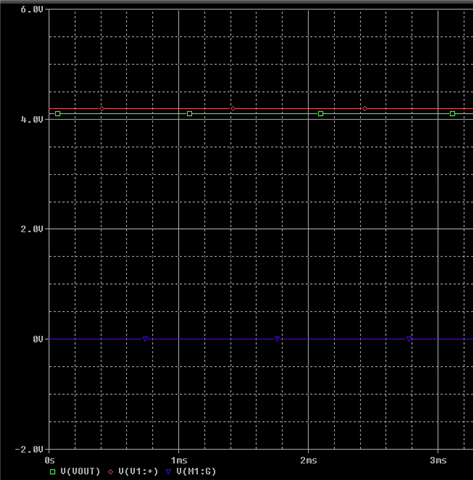
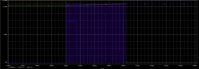
  • yeah my bad, DR should go to mosfet gate and COMP to RC filter. I tried updating the design and running simple transient simulation, but result was still off. It seems like the model doesn't work properly. My input is 3-4.2 V (li-po battery), and output should be  6-36 V (controlled via switch) 100 mA max. Right now I am trying to simulate 4.2 V input, 23 V output, but I get 4 V at the output after simulating. Also I see no switching on Mosfet gate.

    Could you please verify that model works how it should and I can simulate output voltages based on design? Right now I am trying to use unencrypted Pspice model, but I have tried using both and they seem to work the same. What could be the problem?

  • Hi Dominykas,

    Could you give me some additional design specs:
    Vin: 4.2V
    Vout: ??
    Max Load: ??

    Based on the feedback divider selected, the target output voltage would be below the input voltage, so the device never becomes active.

    We also have a quickstart calculator design tool for LM3488, which helps in calculating compensation, feedback divider, etc.
    https://www.ti.com/tool/download/LM3478-88-BOOST-CALC

    Best regards,
    Niklas

  • our project uses different voltages as output. So Vout:6-36V, on current set up, I expect to get 23 V. Based on formula on datasheet, voltage divider seems to be correctly selected, but simulation does not work properly. 

  • Hi Dominykas,

    The reference voltage of LM3488 at the FB pin is 1.26V.
    To achieve 23V on the output, with a high side resistor of 464kOhm, the low side resistor would need to be 26.9KOhm.
    The schematic shows a 274kOhm resistor, so one decade too large.

    Best regards,
    Niklas

  • Thanks for that, it was indeed a mistake in schematic I got, now double checked everything and it seems to be ok. But I still get around 4 V at the output. Although, now I get switching for some time, but still it seems that something is wrong.

    I am sorry for asking, but I have never used Orcad and don't really know how to solve these problems or how to use provided Pspice model. I am just using tutorials info and some experimenting to get this circuit working, could you please provide a step by step tutorial how to correctly import a model, which one should I use (encrypted or unencrypted) and how to run simulation to get output voltage reading and output current? 

  • I can send you my project if this would make it easier to help me solve all the issues. 

  • Hi Dominykas,

    Is there a simulation software you are more comfortable with?
    Then it should be possible to take the unencrypted netlist of the LM3488 model and transfer it to another simulator of your choice.

    You can also send me your simulation files and I will double check the schematic and simulation settings from my side.
    You can attach them directly here in the thread.

    Best regards,
    Niklas

  • hey, mostly I use LTspice to do simulations, so if you could provide LTspice model that would be super great. I will also attach my Orcad project. Thank you for your help!project_sim.zip

  • Hi Dominykas,

    Thanks for attaching the project.
    I ran some simulation and my side and checked all signals.
    All conditions for the device to start switching are met, still, I see the same behavior that there is no gate driver signal.
    I cannot explain why the device seems to start switching and then directly stops without turning on again.
    I currently assume this is a problem related to the internal modeling of the IC, so it cannot be fixed through external circuits.

    Looking into the model internals and fixing the model may take a longer period of time. (As we a currently under high workload, I would even expect it to take several weeks)
    If this is a problem with the model itself, it would not work out to transfer it to LTSpice, as the same error would appear.

    I will update you as soon as the model has been fixed.
    I am very sorry for this inconvenience.

    Best regards,
    Niklas

  • Hello, thank you for that. I am looking forward to the update in this model.

  • Hello, any updates on fixed model? 

  • Hi Dominykas,

    Unfortunately, the update on the LM3488 PSpice model takes more time and is not finished yet.

    Best regards,
    Niklas