This thread has been locked.

If you have a related question, please click the "Ask a related question" button in the top right corner. The newly created question will be automatically linked to this question.

TAS6584Q1EVM: Schottky diodes output diodes and load diagnostics

Part Number: TAS6584Q1EVM

Tool/software:

Hi,

I am going to operate the device with

  • 36V PVDD 
  • 480Khz
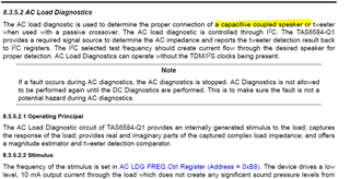
  • capacitively coupled load with 1000uF bipolar capacitor
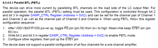
  • PBTL on output 3 & 4 and 1 & 2 output not connected.
  • 5-8Arms output capability

The EVm reference design doesn't include a Schottky diodes, could I please request the design sizing requirements for these diodes knowing the given above?

With PBTL configuration on 3&4 output (capacitively coupled) and an output pair not connected, how would the the device proceeds to Play mode if the DC or AC diagnostic is turned ON by default and test for open load?.

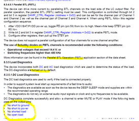
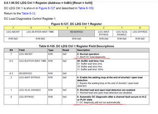
Is their a way to not test or bypass for open load during DC diagnostics?

  • Hi Jose

    In register 0xB0. Abort DC load diag could stop the start up load diag. Bypass DC diag could stop the automotive diag when device leave Sleep mode.

    could I please request the design sizing requirements for these diodes knowing the given above?

    The diode could consider B250A-13-F.

  • HI Shadow,

    thanks for responding quickly. I will implement as per steps above.

    BTW, if out_1x and Out_2x will not be used, how I will terminate these pins?.. leave it open?

    Jose

  • Hi Jose

      Could leave them open, and always set them into Sleep mode in the register.

  • Hi Shadow,

    I have the TAS6584EVM with me and playing around with it with BTL mode and it is working perfectly with PPc3 and my own I2S  micro generating sine wave for channel 1. When I have configured to PBTL as per PPC3 "IO configuration" and shorted the J11 +1 and -1pin /  +2 and -2pin  and put the a 2ohm load across the J11 combine pins of 1 and 2, I couldn't make the board output the sine wave that I have successfully done on BTL mode. I did also reduce the PVDD < 14.4 volts to ensure that I don't need external schottky diodes to perform this PBTL and still with no success. I have now couple of question below.

    • On BTL I only transmit on the left channel and just disregard the right channel. On PBTL, do I need to transmit in the opposite of the left channel? Can I just transmit left and right channel exact data and manually adjust channel 2 to 180°?

    • If I chose PBTL on channel 1 and 2 does the delay enabling to play channel 1 and then 2 on "Device Monitor & Control" I believe is causing an issue. Does the PBTL channel should have one consolidated control to sync both channel for proper operation?.

    Jose

  • Hi Jose

    On BTL I only transmit on the left channel and just disregard the right channel. On PBTL, do I need to transmit in the opposite of the left channel? Can I just transmit left and right channel exact data and manually adjust channel 2 to 180°?

    For I2S format, PBTL will use left CH as parallel 1/2 audio, and right CH as parallel 3/4 audio.

    If I chose PBTL on channel 1 and 2 does the delay enabling to play channel 1 and then 2 on "Device Monitor & Control" I believe is causing an issue. Does the PBTL channel should have one consolidated control to sync both channel for proper operation?.

    If successfully configured into PBTL, CH 1/2 will have the same PWM phase, and CH3/4 will have the same PWM phase. 

    I think maybe you missed a part in the datasheet, that PBTL using requires to follow a correct sequence, as below.

  • thanks for the tip. I will use the sequences switches S1-S4 on the board to comply with the configuration sequence that you have attached..

    BTW regarding the bits on the left and right channel. I know from the I2S format you can select upto 32bit word length but that is not the case of the actual bits that the device will process on its outp/n?. what is the maximum bit that the device able to process without distorting or no output at all?. I have experimented on this and 28bit signed is working correctly. This is not well documented on the datasheet..

  • Hi Jose

      I put a picture of AP settings as below. 

      The Word Width, or maybe call it Slot Size, Word Length. Is the total length of every Slot/CH. This value will decide the clock ratio, for example the usual 32bits setting, will make BCLK = 64*Fs. Most of the audio device have strict requirement of clock ratio, TAS6584 only accept ratio of 64 and 32, it means you could only set 32 or 16 in it. Otherwise device will report clock fault.

      But I think you are talking about Bit Depth, or could call it Effective Bit, since you said tried with 28bit. This is not important. TAS6584 will always use the whole 32bit/16bt value, doesn't care what is the real Bit Depth. I2S is MSB first, the Bit Depth usually not affect the output at all.

      Unless you really want to use a extremely small Bit Depth like only 4bits or 5bits? Your output will looks like a stair. But device won't report clock fault, still works fine.