This thread has been locked.

If you have a related question, please click the "Ask a related question" button in the top right corner. The newly created question will be automatically linked to this question.

LM5008A: Please check switching frequency

Part Number: LM5008A
Other Parts Discussed in Thread: DRV8350

Tool/software:

Dear Ti Team

Actually i'm using DRV8350 Device. LM5008A is included in DRV8350.

so, i have question about LM5008A switching frequency

the bellows is my setting information.

* Vin : 48V

* Vout : 5V

* FSW : about 111KHz

* Inductor : 220uH

i measured switching frequency. but i think that i can not understand the result about switching waveforms.

the result is..

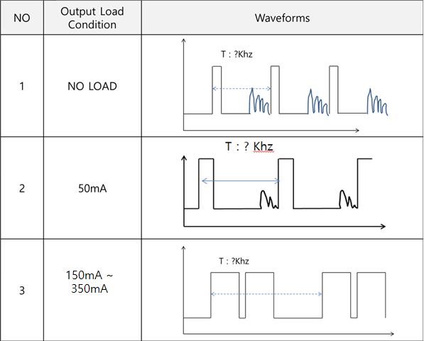
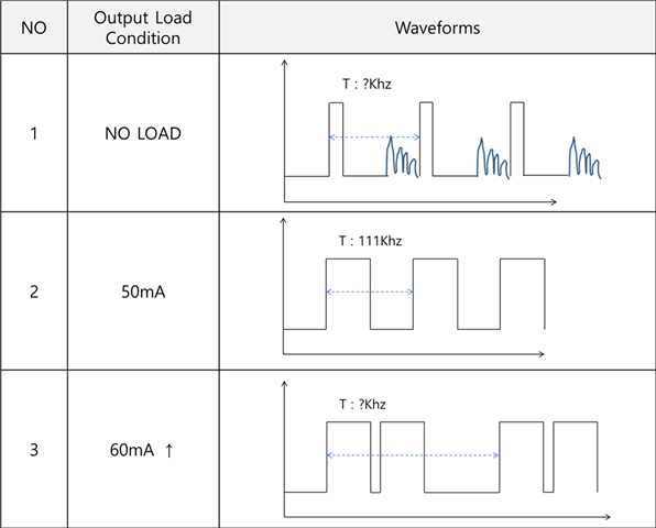
1. no load condition : i think it is okay. it seems like DCM waveforms.

2. 50mA Load condition : i think it is okay. it seems like CCM waveforms.

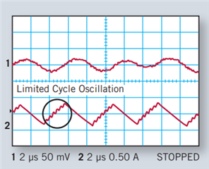
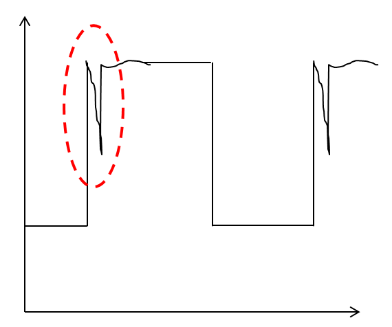
3. Above 50mA Load condition : i think it is wrong, The PWM waveforms appear to overlap

Please refer attached file about No.3 problem.

i'd like to know if No.3 is normal situation.

Please understand that the waveform will be delivered in the form of a picture instead of a capture.

Thanks & Regards

David lim

  • Hello David 

    It looks like your are seeing 'limited cycle oscillation' issue which is caused by not enough voltage ripple at the FB pin. 

    Please download Quick Start at https://www.ti.com/lit/zip/snvu071 and  input your electrical requirements and component selections. 

    Also, please share the schematic and the completed Quick Start file for my review. 

    -EL 

  • Dear EricLee

    Thank you for your reply!

    what is mean of 'limited cycle oscillation' ? could you explain " enough voltage ripple at the FB pin" in detail?
    because of security issue..I can not share sch. file. sorry about that

    but I can tell you about the values like bellows..
    * RFB1,2 : 3.01K
    * RT : 330K
    * L1 : 220uH
    * RCL : 300K
    * R3 : 1ohm
    * COUT : 22uF
    * CIN : 222.3uF (because of DC Link Cap)
    * CBYP : 0.1uF
    * CVCC : 0.47uF
    * CBST : 0.01uF

    * Vin Max : 80V
    * VOUT : 5V
    * FSW : 109Khz
    and I will make new version PCB about this Board.
    and I applied the values like bellows.
    * RFB1,2 : 3.01K
    * RT : 280K
    * L1 : 220uH
    * RCL : 715K
    * R3 : 0.82Ohm
    * COUT : 22uF
    * CIN : 178.3uF (because of DC Link Cap)
    * CBYP : 0.1uF
    * CVCC : 0.47uF
    * CBST : 0.01uF

    * Vin Max : 80V
    * VOUT : 5V
    * FSW : 129Hz
    Then, After testing the new version PCB, and i'll share the waveform about FSW.

  • Hello David 

    The oscillation frequency and the amount of ripple is limited when the Limited Cycle Oscillation happens. Pleas see below

    Please refer https://www.ti.com/lit/an/snva776a/snva776a.pdf while you are preparing the waveforms. Also please send me the completed Quick Start excel file together with he waveforms. 

    -EL

  • Dear Eric

    Today, I tested the new version board.

    but, something is wrong..

    The same problem happened, but the result is a little different. Like below.

    Even if the load increases, it does not change to the CCM mode...

    When load is 50mA, it was still DCM mode. But it has a little less ripple after the square wave than without load

    please check calculation file and please let me know how to solve this problem.

    Thanks & Regards

    David Johnson.

    LM5008AQuickStartCalculator_second version.xls

  • Hello Johnson

    I think #1 and #2 waveforms are normal. I think these are normal operations in DCM.

    About #3, I still think you are seeing the limited cycle oscillation. Please increase R3 and check if any improvement.  

    -EL 

  • Hi EricLee

    Today, I tested again.

    Finally I found the solution.

    I changed to change R3 value 0.82ohm to 3ohm. but the problem is still existed.

    Actually, I added more Capacitor at voltage output node(4.7uF 1ea, 10uF 1ea) besides 22uF(Cout),

    because ouput voltage ripple was littie high (about 10% @5V output)

    so, I deleted the output 2ea capacitor, then i think it is cleared the Limited Cycle Oscillation problem.

    At about 60 mA or more, I could see CCM mode.

    1. But, i think that the waveform of FSW is someting wrong.

    Does the LM5008A have Spread Spectrum function?

    because waveform of FSW shakeed a lot from side to side. like spread spectrum.

    and switching frequency was also wrong. i set the FSW value 129Khz. but i could check about 150~165Khz FSW in waveform.(When CCM,DCM all)

    2. and i have another question.

    When the motor is operated, the 5V output noise is slightly increased. so, a capacitor should be attached to the output node,

    and this IC cannot be attached because it is S-O-T BUCK CONVERTOR, and because of the limited cycle oscillation problem.

    Please let me know what to do.

  • Hello Johnson 

    1. The device doesn't have spread spectrum function, but the switching frequency shakes by the nature of COT topology. The switching frequency variation of COT device is larger than normal fixed frequency PWM devices because COT device controls on-time not the switching frequency

    2. I guess you are asking about the output capacitor location. If you need, you can split a large output capacitor into multiple small size capacitors and locate them at the places you need. 

    -EL 

  • Dear EricLee

    Thanks! I understood your answer.

    and I have last question.

    when CCM mode, If I zoom in on the FSW waveform, a Vripple is observed as shown in the figure below. Is this a normal phenomenon?

    If it's not normal, how should I improve it? 

    Please let me know.

    Thanks!

    J.D

  • Hello JD 

    Would you please send me the screen captures ? Please capture VIN, SW, and inductor current together. I guess you are observing DCM waveform, but it might be caused by other reason. 

    -EL