This thread has been locked.

If you have a related question, please click the "Ask a related question" button in the top right corner. The newly created question will be automatically linked to this question.

TPS23523: About the starting sequence

Part Number: TPS23523


Tool/software:

Hi,

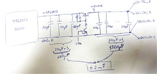
I am using the TPS23523 in a design to protect the DC input from -37VDC to -60VDC with nominal -48VDC.

Design data are attached in the excel file. 

TPS2352X_Excel_Tool_Web_RevB_prueba4.xlsx

Adittionally, I am using the pins Neg48 and Bgate with two 2 N-channel mosfet in parallel (IPB110N20N3LF). 

For gate pin, it is used N-channel MOSFET (IPB110N20N3LF) and for gate2 pin theCSD19535KTT.

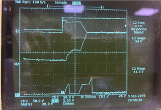
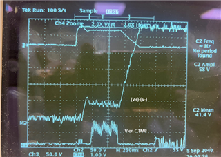
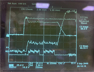
I have checked the signal in the output of TPS23523 in the starting sequence when 3 different DC power signal of -37VDC, -48VDC and -60VDC are connected to the input of TPS23523.

Please, find attached the different figures.

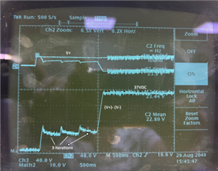
a) Waveform for 37VDC

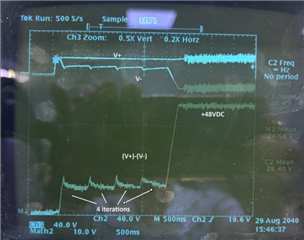
b) Waveform for -48VDC

c) Waveform for -60VDC

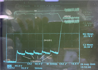
In these figures, it is observed a different waveform fdepending on the input voltage value and a waveform is repeated several times (3 iterations for  -37VDC, 4 iterations for -48VDC and 5 iterations for -60VDC)

Which is the cause of this repeated waveform?  It seems that "something" is not right and the sequence is repeated. . 

Please, could you indicate us if this repeated waveform  is "typical"? If this repeated waveform are not "usual", please. how can I solve it?

Thanks in advance.

Best Regards,

Pedro

  • Hi Pedro,

    Thanks for reaching out. I will get back by this Friday.

    BR,

    Rakesh

  • Hi Pedro,

    It looks like the inrush time period is expiring with large Cout. 

    Can you change the Cout from 2mF to 100uF and test again.

    This helps to root-cause the problem.

    BR,

    Rakesh

  • Hi Rakesh,

    OK, I will checked reducing Cout as proposed next Monday and it will send the results.

    I have checked to increase the Css (Capacitor soft start) from initial value 110nF to 210nF (added a paralllel 100nF) and the number of iterations in the starting process is reduced to 1 or 2 instead of 4 or 5. 

    Thanks in advance.

    Best Regards,

    Pedro

  • Hi Rakesh,

    I have tested the output with Cload= 3 x 220uF =660uF y the results are OK, the iterations have disappeared and only a ramp up voltage waveform appears.

    Please, see attached figure below:

    I need Cload about 2mF because the output of TPS23523 supplies the inputs of several DC-DC converters which require high capacitance for EMC filter.

    How can you solve this problem?

    Thanks in advance.

    Best Regards,

    Pedro

  • Hi Rakest,

    Please, find below the total circuit.  Cout = 660uF are directly connected to the output of TPS23523 but other capacitors (1320uF) are connected using a switch (P channel transistor). When TPS23253 have been started and +48V is in its output and close the switch, several iterations occur again and when DC-DC are activated and have a consumption, the TPS23523 is constantly re-started. I think that there is a problem when the step of current (inrush current of capacitor or consumption from the starting of DC-DC converter.)

    The next figure occurs when the switch (P channel mosfet ) is closed and the DC-DC converter starts to require current, then the TPS is restarted.

    Thanks in advance.

    Brst Regards,

    Pedro

  • Hi Pedro,

    Can you probe the input current and TMR voltage. we need to check whether the startup current is below Ilim2 value 1.5A or not. 

    Please enable downstream DC-DC with PG output as shown below.

    Best Regards,

    Rakesh

  • Hi Rakesh,

    The problem of continuous restart, when current from DC-DC is required, is solved delaying the enable signal for DC-DC converter.

    A circuit similar to the indicated was already used, PG signal from TPS23523 was used to enable the DC_DC converters. But an adittional delay was necessary. I have added several capacitors in the enable circuits to delay the enable of DC-DC converters and then the problem is solved.

    On the other hand , I have tested some points.

    a) I have checked the SS pin to try to reduce Inrush current and to avoid to reach the current limit to trip(0.75A)

    Figure 1 : Css=100nF Css,vee=330nF  --> Inrush current = 0.5A (Failute in starting process)

    Figure 2: Css=300nF Css,VEE=990nF --> Inrush current = 0.5A (Failute in starting process)

    b) We have checked the V TMR. it seems that reach the 1.5V and times out during 64 cycles.

    If the problem is current limit (0.75A), PROG pin can be in float (Now is connected to VEE), the the current limit increases from 1.5A to 3A with 1mohms for sense resistor. High limit is increased from 20A to 25A.

    Another proposal could be increase the VD when the two limit currents are switched, currenlt is 20V but this could be increased if required.

    What do you think about this?

    Thanks in advance.

    Best Regards,

    Pedro

  • Hi Pedro,

    Increasing lower current limit threshold or reducing VD should help. For any change, please plug-in corresponding values in design calculator and verify SOA.

    Best Regards,

    Rakesh