Tool/software:
Dear TI team,
Greetings of the day...
We found PFC mosfet getting fail at initial switch ON condition. we found at input 90degree phase angle mosfet current rising to >30A but at 0 or 10 degree phase angle <10A only.
Please look into problem and give us solution. please let me know if any details required.
0 Degree 90 Degree


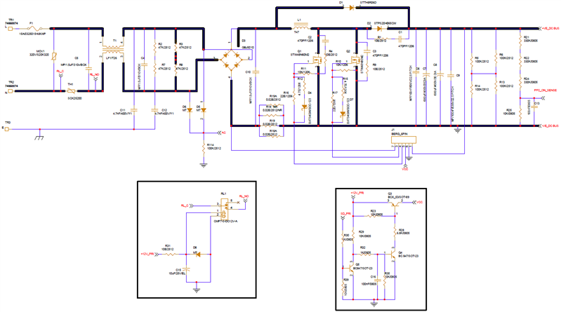
Design details:
2.4KW
400V@6A
two mosfets in parallel(STW48N60M2)
820uH inductor
60KHz
Regards,
Prathap M