A related question is a question created from another question. When the related question is created, it will be automatically linked to the original question.
If you have a related question, please click the "Ask a related question" button in the top right corner. The newly created question will be automatically linked to this question.
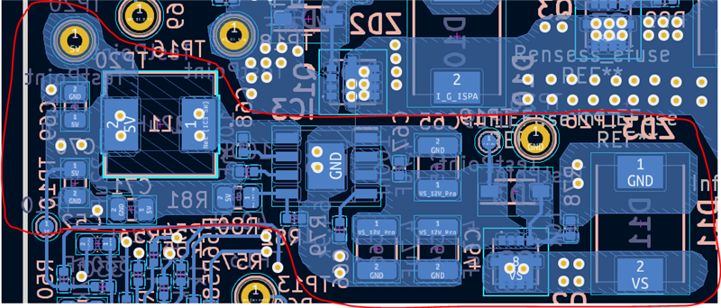
I would shift bootcap Cout11 closer to the switch node by lessening the trace length and making the boot trace should be as wide as possible connecting the BOOT and SW pin.
By doing so, you can shift the inductor L1 closer to make the SW node smaller. This will also bring in the output capacitors closer.
I recommend also connecting the 5V output node using big traces to minimize adding extra inductance to the circuits downstream.
It looks like you have added a solid ground layer underneath top and bottom layers, so I think it should be ok.