This thread has been locked.

If you have a related question, please click the "Ask a related question" button in the top right corner. The newly created question will be automatically linked to this question.

BQ34210-Q1: Not able to set full charge capacity in BQ34210-q1 using I2C interface

Part Number: BQ34210-Q1
Other Parts Discussed in Thread: BQSTUDIO

Tool/software:

Hello Team,

We have a custom module where we are using BQ34210-q1 fuel gauge. But we are able to set Design Capacity range. But when we tried to set Full charge Capacity it is not changing. We confirmed it by reading ,  "FullChargeCapacity(): 0x12 and 0x13 and DesignCapacity(): 0x3C and 0x3D" but when we read Full charge capacity it only shows 2200mAh. Which is default value set during POR. 

Kindly let me know which step I need to follow for changing full charge capacity. It is needed to calculate remaining capacity of the battery.

Thank you

  • Hi,

    this is a read only parameter, this is not a parameter you set.

    The gauge updates unfiltered FCC at any one of the following events:

    • After a full reset
    • Start of charging
    • End of charging
    • Start of discharge
    • DOD grid point cross during discharge
    • Change in Temperature
    • SOH update
    • When OCV measurement is taken
    • When Qmax updates

    Regards,

    Evan

  • Hello Evan,

    Thank you for your response

    I tried the above steps.

    The the value of Full charge capacity is not changing.

    We are setting the Design Capacity to 10000 mAh

    and the current to 3.7 which is default

    But when we read the remaining capacity it starts from 3950 mAh

    and Full charge capacity it is showing 2200 mAh.

    And relative State Of Change will not change because Full Charge capacity is less than Design Capacity so it always shows 0.

    Kindly guide us to the steps as per the document which we are following for BQ34210-q1 (sluube8.pdf).

    In this document they have given that initial value for Full charge Capacity is directly copied or same as ROM CEDV profile. 

    I have shared the screenshots of the points I have mentioned above

    Thank you.

  • Hi,

    Can you share your .srec?

    Can you also share a log file of the Remcap/FCC/SOC error?

    Was the FCC corrected after a valid learning cycle.

    Regards,

    Evan

  • Hello Evan,

    We don't have BQ34210-q1 EVK with us. And we are not using BQStudio for configuration and readings.

    We manually configuring with TI MCU using I2C commands. 

    The problem is that we are able to configure Design capacity value, but not full charge capacity value.

    We tried both the profiles in 1st profile the design capacity value will be default set to 2200 and in 2nd it is 1400.

    We are unable to update using config method. 

    For full charge capacity we are configuring by using below commands

    Wr 0xAA 0x00 0x14 0x00

    Wr 0xAA 0x00 0x72 0x36 //Unsealing

    Wr 0xAA 0x00 0x90 0x00 // Entering Config mode

    //will be checking the operation status by reading 0x3B

    //Once it entered to unseal 

    Wr 0xAA 0x3E 0x47 

    Wr 0xAA 0x3F 0x93

    Rd 0xAB 0x40 0x08 Reading OLD MSB value

    Rd 0xAB 0x41 0x98 Reading OLD LSB value

    Rd 0xAB 0x60 0x2E Reading OLD Checksum

    Rd 0xAB 0x61 0x24 Reading OLD Length

    I want to set the full charge capacity to 10000 mAh

    so my value will be 0x2710

    Wr 0xAA 0x40 0x27 

    Wr 0xAA 0x41 0x10 //Writing New MSB and LSB values

    Wr 0xAA 0x60 0x97 // New checksum value as per the calculation

    Wr 0xAA 0x61 0x24 //Writing new checksum length

    Wr 0xAA 0x91 0x00 // exiting config mode

    Wr 0xAA 0x30 0x00 //Sealing

    The above command is used to configure or change the Full charge capacity 

    But when we read the 0x12 and 0x13 we are not able to read changed value. It still be the default one 2200 mAh.

    And I want to know what are all the steps to start learning cycle for BQ34210-q1. 

    Thank you.

  • Hello Evan,

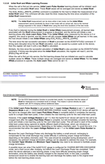
    we are following the below procedure as given in datasheet. 

    Thank you

  • Hello Team, 

    My issue is not resolved. Kindly change the status. 

    Is there any auto raising flags for resolved and unresolved. I haven't told its resolved. How can the forum close it please make it open. 

    Thank you.

  • Hi,

    I cannot change the TI resolved once pressed but I have the thread still marked as open on my end so I will continue to get notifications and provide help until we solve your issue.

    The problem is that we are able to configure Design capacity value, but not full charge capacity value.

    FCC is not something you configure it is calculated from the gauge. 

    If you have followed the steps and updated design capacity FCC will update upon a successful learning cycle.

    TRM: 1.3.3.8

    Regards,

    Evan

  • Hello Evan,

    Thank you for guiding us on the right path.

    We tried initiating learning cycle. But I believe it is failing.

    First we have initiated device reset

    and then we given EOS_START_LEARN

    and then whatever you have told us to do.

    EOS_RCELL_RRATE_LEARN. and then we had set Design capacity value.

    Then we stoped learning by giving EOS_ABORT_LEARN command.

    And we tried to read the full charge capacity it is still showing standard value. 2200 mA.

    Will you please guide us the steps from the beginning from where we have to start and where we have to end. 

    I am new to this fuel gauge and we dont have EVK so that we could have tested with BQStudio.

    But we have a custom setup where we can control and configure the fuel gauge using I2C commands from MCU.

    I still didnt understood about  Alert Config Registers. These register we have to write or we need to read from these register's. 

    And about learning cycle I have zero knowledge. I dont even understood which registers I need to write and which to read the status.

    Kindly please help me solving these issue.

    Our target is to set the Design capacity value, initiate learning cycle and read the remaining capacity using the learned data. 

    About the EOS Learning I have zero knowledge.

    Please let me know the registers which I need to write. So that I can archive the expected outcome. Our main intension is to make it possible to read full charge capacity using EOS_LEARNING. Kindly guide us.

    Thanking you.

  • Hello Evan,

    After some practices I was able to start EOS Learning by providing EOS_LEARNING_START. And I read EOSLearnStatus and LCMD flag was made high.

    But after I updated Design capacity, I wanted to check whether the learning phase have been successfully completed.

    Again, I tried reading EOSLearnStatus. But now LFAULT and LUCD flags have been raised. I just wanted to understand why these flags are raise.

    I know because of LUCD flag the Learning phase was aborted. But I don't know what cause the LUCD flag to change its state. 

    Kindly let me know what could be the issue. And where we are missing.

    Thank you

  • Hi,

    The LUCD flag sets when the discharge or charge threshold currents are exceeded in the learning phase. 

    Regards,

    Evan

  • Hello Evan,

    I understood the concept but how we can Set discharge and charge threshold currents.

    And whatever we are following is correct or not that also I wanted to clarify.

    Initially I will reset the fuel gauge

    I will enable the EOS_EN

    I will start EOS_LEARN_START

    I will read EOSLearnStatus()

    here I am able to read LCMD flag been raised

    I will start EOSRCELLRRATELearn()

    I will update Design Capacity using conf update to 10000mA

    I willl read the DEVID

    I will check the Voltage()

    I will set the BLTDischargeSet() to 8000mA

    I will read Remaining Capacity()

    I will read fullChargeCapacity()

    Then I will read EOSLearnStatus()

    Here I can see LFAULT and LUCD Flags are been raised.

    Kindly let me know what mistake I am making in the above pattern.

    Thank you

  • Hi,

    Please set both chg/dschg thresholds, design capacity, etc before starting the learning phase. 

    Do you need help writing to the gauge?

    Using I2C Communications With the bq34110 bq35100 and bq34z100-G1 Series of Gas

    Gauge Communication

    Any fault flags that are raised are usually due to a mistake in configuration.

    No fault flags should be raised during the learning process.

    Regards,

    Evan

  • Hello Evan,

    Thank you for your response.

    I still cant understand the pattern I need to follow. 

    The document you have shared given me a vast amount of knowledge. Thank you for the information Evan.

    But I have a problem the document uses .fs file which only can be generated from BQSTudio.

    I have now understood that we need to set chg/dschg thresholds, and design capacity before starting the learning phase.

    But I failed to understand which register I need to write so the chg/dsg threshold's can be changed.

    Kindly help me to understand the pattern. Which of these register's I need to write ?

    Thank you

  • Hi,

    You are looking for chg/dschg current threshold,

    Regards,

    Evan

  • Hello Evan,

    Thank you for letting me know the register values to be written. 

    I have a new problem now.

    Discharge Detection Threshold and Charge Detection Threshold values can be changed using config mode, right?

    When I tried to read the old checksum, it is returning different values every time and because of that I am not able to change Charge and Discharge Detection Threshold values. 

    And when I tried to read OLD MSB and Old LSB values some time it will return default value as given in technical document. But sometimes it will return 0, which is in my perspective wrong. 

    Kindly let me know why the checksum value will be changing. And kindly let me know why sometimes the default values are not returned. 

    Thanking you.

  • Hi,

    Yes, you need to be in config update mode.

    I am unsure what you are doing incorrectly, can you share your .srec and the values you would like to write for the threshold.

    Regards,

    Evan

  • Hello Evan,

    Sorry to Say that we don't have EV2300 with us. So, we are unable to generate .srec file using BQStudio. I can Share you the required values, actually we want to set for the configuration. 

    We have a battery which has a capacity of 10000mAh

    and discharge of 0.2C 

    charging threshold is 2000mAh

    The voltage to be set is 3.7v

    I will share you the steps we are following to configure discharge current threshold

    Wr    0x00 0x14

    Wr    0x01 0x04

    Wr    0x00 0x72

    Wr    0x01 0x36     // Unseal 

    Wr    0x00 0x90

    Wr    0x01 0x00     // enter config update mode

    Rd    0x3B             // until bit 4 is set

    Wr    0x3E 0x84

    Wr    0x3F 0x92

    Rd    0x60             // reading old checksum

    Rd    0x61             // reading old checksum length

    Wr    0x3E 0x84

    Wr    0x3F 0x92

    Rd    0x40             // Reading OLD MSB

    Rd    0x41             // Reading OLD LSB

    Wr    0x40 0x07    // Writing New MSB

    Wr    0x41 0xD0    //Writing New LSB

    Wr    0x60 0x25    // Writing new Checksum

    Wr    0x61 0x06    // Writing new checksum length

    Wr    0x00 0x91 

    Wr    0x01 0x00    // Exiting config update mode

    Rd    0x3B             // until bit 4 is cleared

    Wr    0x00 0x30

    Wr    0x01 0x00    // Sealing 

    These are the pattern we are following to change the discharge current threshold value.

    But if I read it again, we are observing the same default value set which is 60.

    Kindly let me know what mistakes we are making.

    Thank you

  • Hello Evan,

    We are configuring bq34210-q1 using I2C commands from TM4C123 MCU not with BQStudio. To generate .srec we need EV2300. We don't have EV2300. We have to configure manually using I2C.

    Thank you

  • Hello Evan,

    This is our battery specifications

    Thank you

  • Hi,

    Understood, please allow me sometime to return to the office, I can help with this when I return to the lab.

    Quick question, have you been able to write any values to the device?

    Regards,

    Evan

  • Hello Evan,

    Yes, we are able to write only design capacity value to the device. That also we worked on what will be the default checksum value and we calculated as per that and so whatever the old checksum is it will write as per right calculation we made every time on reset if it is giving wrong old checksum also it will write. 

    The issue is 

    1. Old Checksum is not consistently same every time.

    2. We are not able to write other values like Discharge current threshold and Charge current threshold values.

    3. We are not able to complete EOS Learning cycle.

    Kindly need your help.

    Thank you

  • Hi,

    Are you calculating the checksum correctly?

    Regards,

    Evan

  • Hello Evan,

    Actually we have figured it out how to write the value for Charge Detection Threshold and Discharge Detection Threshold and Design Capacity values to the device.

    Could you please let us know. What we have to do next?

    Like I tried these things

    EOS_EN()

    EOSStartLearning()

    EOSLearnStatus()

    EOSRCELLRRATELEARN()

    But I dont know whether this is right or wrong steps to Start Learning process.

    And please let me know when we will notice LDONE bit enabled.?

    And please let me know before Starting EOSLearnStart phase do we have to write something else?

    Thank you.

  • Hi,

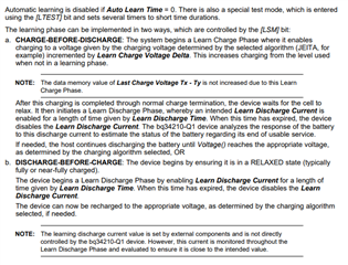
    Chapter 1.3 in the TRM, linked below, goes over the learning cycle. Please let me know if you have any question.

    bq34210-Q1 Technical Reference Manual (ti.com)

    Regards,

    Evan

  • Hello Evan,

    Now we are able to Start the EOS Learning Phase. And we made ACCUM_CHG_EN disabled. So in EOSLearnStatus we can start DISCHARGE-TO-CHARGE is enabled.

    And we are able to set LTEST.

    Please let us know what we have to do next to complete Learning phase.

    Thank you

  • Hi,

    There are 2 ways to complete the learning phase, charge-before-discharge or discharge-before-charge, both are documented in the chapter 1.3 of the TRM.

    Please identify which method you would like to use and what questions you have.

    Regards,

    Evan

  • Hello Evan,

    We have successfully configured the Discharge detection threshold and charge detection threshold for 2000mAh

    And we have configured Design capacity value for 10000mAh

    And we have set EOS configuration as LTest - 1, LVR - 0, LSM - 1

    So DISCHARGE BEFORE CHARGE Phase

    Then we have written FCC-LIMIT as 1 in Gauging configuration and all the bits 0 

    And we have set Near Full to 9900mAh

    And Quit Current to 1000mAh

    Now we are successfully abled to start Learning phase by giving EOS_EN

    We have started EOS_START_LEARN()

    But when you read the EOSLearnStatus()

    Sometime VDQ flag is not enabled when I read operationStatus()

    The learning is started, and it is entering LRLX phase (Relaxation Phase)

    So we can observe LRLX flag been raised EOSLearnStatus()

    But I can't observe [REST] flag in Gauging Status() //So Relaxation mode not entered successfully

    So we are not able to enter Learn Discharge Mode.

    We are continuously tracking the LDSG Flag in EOSLearnStatus() 

    But after waiting for 10 minutes also it is not entering Learn Discharge Phase

    Kindly need your help.

    Thanking you

  • Hi,

    The rest flag should set when the battery is fully relaxed, depending on the cells this could take 5 hours or longer.

    Please allow the batteries to rest over night and see if the flag sets.

    Regards,

    Diego

  • Hello Diago,

    The battery was in rest all the night, but I was not able to see REST flag been raised.

    It still stays in LRLX mode not moving to LDSG.

    Kindly let me know what we are missing.

    I have set quit current and overload current also.

    But I have failed to understand why it is not moving to discharge phase.

    Please let me know what is that missing point.

    Thank you

  • Hi,

    LRLX is but is not a configurable bit it is set by the gauge.

    Is the gauge in automatic EOS determination mode?

    Regards,

    Diego

  • Hello Diego,

    We know that we cannot configure the LRLX Flag. It will be set by the gauge. My question we are stuck in relaxation phase and not moving to discharge phase. 

    It is entering to relaxation phase as we can observe LRLX flag in EOS Learn Status register

    but it is not coming out of relaxation phase and the battery is not completely relaxed.

    If relaxed the [REST] flag would have raised

    Kindly need help

    Thank you

  • Hello Diego,

    Will you please let me know can I enable automatic EOS determination mode?

    Thank you.

  • Hi Diego,

    I have tried automatic EOS determination today.

    I have enabled determination by giving EOS_EN

    I have set LTEST flag and LSM flag as 1

    and I have given EOS RCELL RRATE Learn command

     Tried reading EOSLearnStatus()

    It will enable only LPER, LRLX flags. 

    I have waited for 5 minutes So I thought it will enter into Discharge Mode (LDSG).

    But nothing happened.

    Kindly need your help in understanding these commands.

    I was also tracking Auto_Learn_Time counter to check. But it is not changing. It stuck at 220 hrs

    Thank you

  • Hi,

    auto learn time is a configurable parameter.


    Once you start discharging your cells the gauge should enter discharge mode.

    Regards,

    Diego

  • Hi Diego,

    I have started automatic learning phase.

    And I have enabled LTEST flag also.

    But you are saying once you start discharging. I didnt get the actual meaning.

    How to start discharge mode.

    And why the learning stuck in LRLX relaxation phase?

    Kindly reply

    thank you

  • Hi Diego,

    I have enabled LTEST flag.

    So the auto learn time will be set as 10 minuetes right?

    So let me know some points

    if you are setting LTEST flag, still auto learn time need to best in memory?

    And if yes, I can see the unit is given in hours. But how much minimum time I need to give to the auto learn time?

    And after entering LRLX how much time does device takes to enter into discharge mode?

    Thank you

  • Hi,

    Discharge your batteries and the flags should flip.

    If you set LTEST then the auto learn time is 10 minutes.

    Regards,

    Diego

  • Hello Diego,

    I have checked it. It is taking more than 10 minutes to enter Discharge mode and it is not constant. And after that I waited for 10 more minutes to let it finish learning. But it didn't. And I observed Auto Learn Time it always shows 1. After making LTEST enable, also the timer has not decreased.

    Whether the Auto Learn Time will decrease or it is constant. Because the reading unit is saying "Hour".

    How much more time it will take to complete the learning phase.?

    Thank you

  • Hello Diego,

    I started Learning phase and it moved to the LRLX and then to LDSG

    And after sometime I could able to see LDONE 

    But I have a new problem now.

    With LDONE I can see few more flags are being raised

    LPER,LCMD,LABRT,LCTO,LUCD,LCTEDGE,LRSTOR

    The above flags are being raised with LDONE.

    And I cant see any changes in FCC after learning been completed.

    It is still showing 256

    And even RC is also constant 1760

    I have set LTEST so the auto learn time and all the other timers been decreased.

    Whether that is causing the issue?

    I have added battery specification with this response

    Kindly let me, what value I need to be set for the device to be working properly

    Like Discharge Current Threshold

    Charge Current Threshold

    Learn Discharge Current etc.

    Kindly help with the values if possible

    Thank you Diego

  • Hello Vinay,

    Diego is currently out of town. He should be able to get back to you later this week.

    Regards,

    Nick

  • Hi,

    It appears you have opened a new thread, I will reply to the new thread and lock this one to avoid confusion.

    Regards,

    Diego