This thread has been locked.

If you have a related question, please click the "Ask a related question" button in the top right corner. The newly created question will be automatically linked to this question.

BQ25890: Question about fault status register (REG0C)

Part Number: BQ25890

Tool/software:

Hi, TI team.
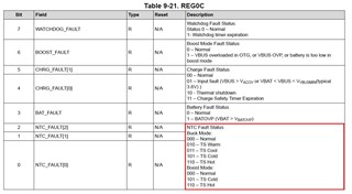
I have a question about BQ25890 fault register (REG0C).

1. I want to know the temperature definition and temperature range of each item (total 8 items below) in case of NTC Fault Status.
I couldn't find those information in the datasheet. 

(1) Buck Mode
 - Normal :
 - TS Warm :
 - TS Cool :
 - TS Cold :
 - TS Hot :

(2) Boost Mode
 - Normal :
 - TS Cold :
 - TS Hot :

For example, when temperature goes down, TS Cool starts at X degC and if it exceeds XX degC, it turnes to TS Cold.
I would like to know what temperature each item is defined as.
ex) Normal : 10~45 degree
TS Warm :  45 degree
TS Cool : 10 degree
TS Cold : 0 degree
TS Hot : 60 degree

2. I would also like to know whether the temperature for each item is fixed or adjustable.


Thank you

Hyunkug

  • Hi Hyunkug, 

    Thank you for reaching out via E2E. Please see my comments below. 

    The temperature thresholds are not fixed. They are determined by the NTC used, as well as, the resistor divider network at TS. The necessary circuit to connect at TS pin is shown in Figure 9-6 on BQ25890 datasheet page 27. 

    Normal : 10~45 degree
    TS Warm :  45 degree
    TS Cool : 10 degree
    TS Cold : 0 degree
    TS Hot : 60 degree

    These values are the expected temperature thresholds using the recommended 103-AT NTC and RT1 = 5.24kohms and RT2 = 30.31kohms. These thresholds are also shown in datasheet Figure 9-7.

    Please be aware we also provide an Excel based tool (bq2589x Calculation tools) to help with resistor selection given desired temperature range. It can be downloaded on the BQ25890 product page on TI.com under the 'Design & Development' section. https://www.ti.com/product/BQ25890 

    Boost mode hot and cold thresholds are set by the same NTC and resistor network, but can be modified further via register settings (REG01). Further details on boost mode temperature range can be found in datasheet section 9.2.7.5.2. 

    Best Regards,

    Garrett 

  • Hi Garrett, 

    Thank you for reply.

    I have additional question about buck mode and boost most.

    1. Which mode is default? buck or boost?

    2. Can I switch from one mode to another? (through register change?) or Do changes only occur if certain conditions are met?

    I would appreciate it if you answer my additional question. 

  • Hi Garrett,

    More questions.

    1. How MCU can check the temperature from charger IC? MCU reads the specific register (ex TS pin related) and check voltage level of TS pin and then convert it to temperature? or any other way?

    2. Can MCU check exact temperature value from charger IC or just knows the ADC value and translate it?

    I want to know the mechanism to check the temperature value through the charger IC.

    Thank you

  • Hi Hyunkug, 

    Please see my comments on your questions below. 

    1. Which mode is default? buck or boost?

    Buck mode is default. Device will charge in buck mode without any additional configuration assuming input source is present at VBUS and /CE pin is pulled low. 

    2. Can I switch from one mode to another? (through register change?) or Do changes only occur if certain conditions are met?

    Required conditions to enter boost mode operation are listed in datasheet section 9.2.5. Input source at VBUS needs to be removed and boost mode needs to be enabled via both OTG pin and OTG_CONFIG register setting. Then to switch back to buck mode just disable boost mode via either OTG pin or register setting and re-apply input adapter. 

    1. How MCU can check the temperature from charger IC? MCU reads the specific register (ex TS pin related) and check voltage level of TS pin and then convert it to temperature? or any other way?

    Correct, MCU code will need to convert the TS pin percentage output in REG10 to temperature value given expected resistance of NTC at a certain temperature. Additionally, REG0C bits 2:0 can be monitored to know whether the device is in normal temperature operation range compared to TS WARM, TS COOL, etc. 

    2. Can MCU check exact temperature value from charger IC or just knows the ADC value and translate it?

    There is not a way for MCU to check exact temperature value from charger IC. BQ25890 adjusts operation based on bias voltage at TS pin, it does not know the exact temperature of the battery.

    Best Regards,

    Garrett

  • Hi Garrett,

    Thank you very much. Your answer was very helpful.

    But I did not understand fully about temperature reading from REG10. 

    Could you elaborate a little more on the relationship between ADC conversion of TS Voltage as percentage of REGN and temperature?

    What's the meaning of each percentage? Is there a fomular?

    I want to know this REG10 table.

    Thank you! 

  • Hi Hyunkug, 

    The conversion of TS voltage as a percentage of REGN to temperature depends on the specific NTC you are using in your system. The TS voltage is controlled by the resistor divider network so voltage % only changes as NTC resistance value changes. 

    In general higher TS voltage % indicates lower temperature and lower TS voltage % indicates higher temperature. To convert from TS voltage % to temperature you will need to use the voltage divider equation to determine the corresponding NTC resistance value for a specific TS voltage % reported in REG10 then map that resistance to its corresponding temperature. 

    Best Regards,

    Garrett