This thread has been locked.

If you have a related question, please click the "Ask a related question" button in the top right corner. The newly created question will be automatically linked to this question.

UCC28C53-Q1: UCC28C53-Q1 controller for two switch forward converter

Part Number: UCC28C53-Q1
Other Parts Discussed in Thread: PMP30183, UCC28C53

Tool/software:

Dear Ti team,

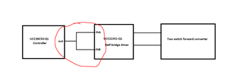
I am looking to use UCC28C53-Q1 as a controller for two-switch forward converter. But i want the overcurrent and overvoltage protection feature also.How i can implement it with Ti component or external component can you suggest it.

  • UCC28C53-Q1 is a general purpose, single-ended PWM controller intended to operate using peak current mode control. This means you inherently get cycle-by-cycle current limiting but there is not overvoltage protection so this would need to be designed externally. PMP30183 is one example of a TI reference design showing the 2-switch forward topology. Also, search "two-switch forward converter E2E TI"

    Steve

  • Hi Steven,

    Thanks for mentioning it but i know it, we have to do from externally only But Just asked is there any reference circuits for overvoltage protection  by TI.

    What about over current protection protection ??

    Checked the PMP30183 but i did'nt found any reference circuits for protection.

    one more query:

    I want to design like below, connecting controller output to two inputs of the isolated half bridge driver for two switch forward requirement.

    can i do like that and there will be no problem know ..can you check and confirm it?

  • Block diagram looks correct. Overcurrent protection is happening as a result of cycle-by-cycle peak current mode control. You can Google it or see many E2E threads such as this recent one here. If you want the PWM to take further OCP (and OVP) corrective action than what is available from the controller, you need to design these circuits externally such as sensing line voltage and using a comparator to shut down the PWM output during OVP. I do not have example circuits to refer but you can Google this also. Since the UCC28C53 is not sensing input voltage, you need to introduce line voltage sensing, you need a way to bias the comparator circuit to make sure it remains active during OVP, OCP shutdown and you need a stable reference to compare the divided down input voltage. I used to work at Collins (UTC/Hamilton Standard) as Analog/Power Supply Designer and these circuits were quite common in many power supply designs. It seems you should be able to leverage some reuse inside your company?

    Regards,

    Steve

  • Hi Steven,Thanks for your suggestion

     i have analyzed it with simulation for OVP and OCP and its done now.going with output resister based sensing   and comparator for OVP and OCP trip 

    Thanks.