This thread has been locked.

If you have a related question, please click the "Ask a related question" button in the top right corner. The newly created question will be automatically linked to this question.

BQ79656-Q1: Not getting 16th cell volatge

Part Number: BQ79656-Q1
Other Parts Discussed in Thread: BQ79616

Tool/software:

Hi all,

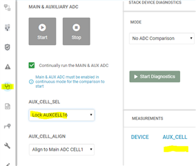
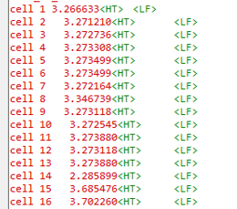
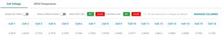
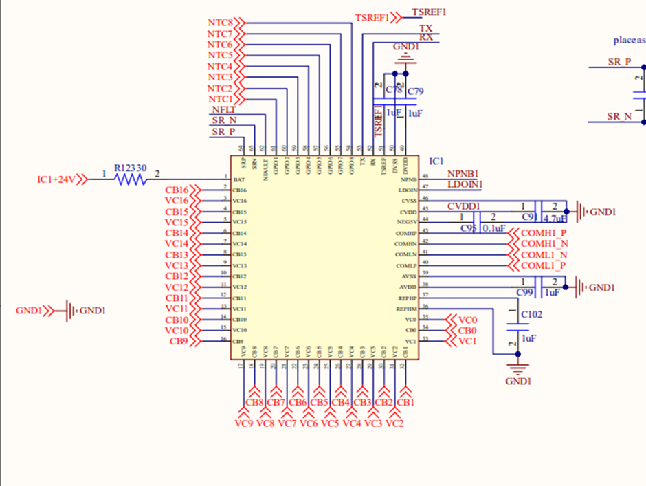
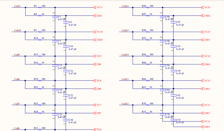
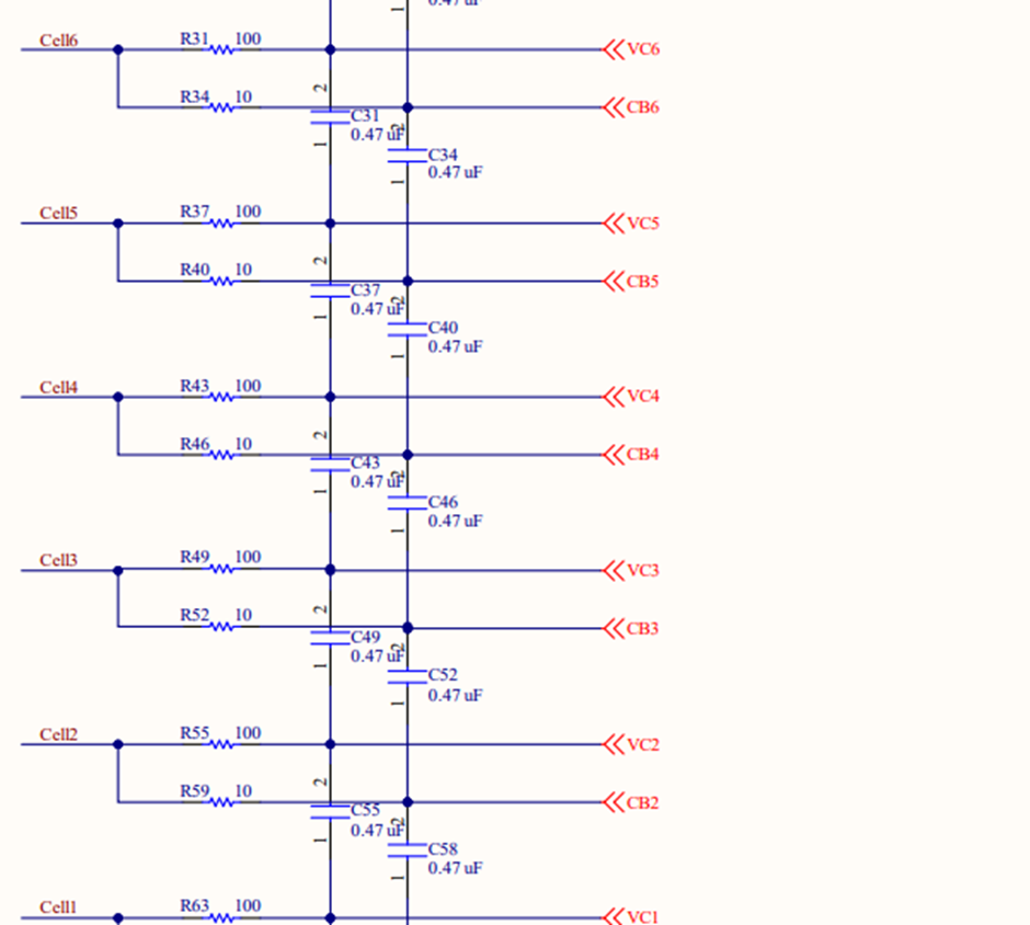
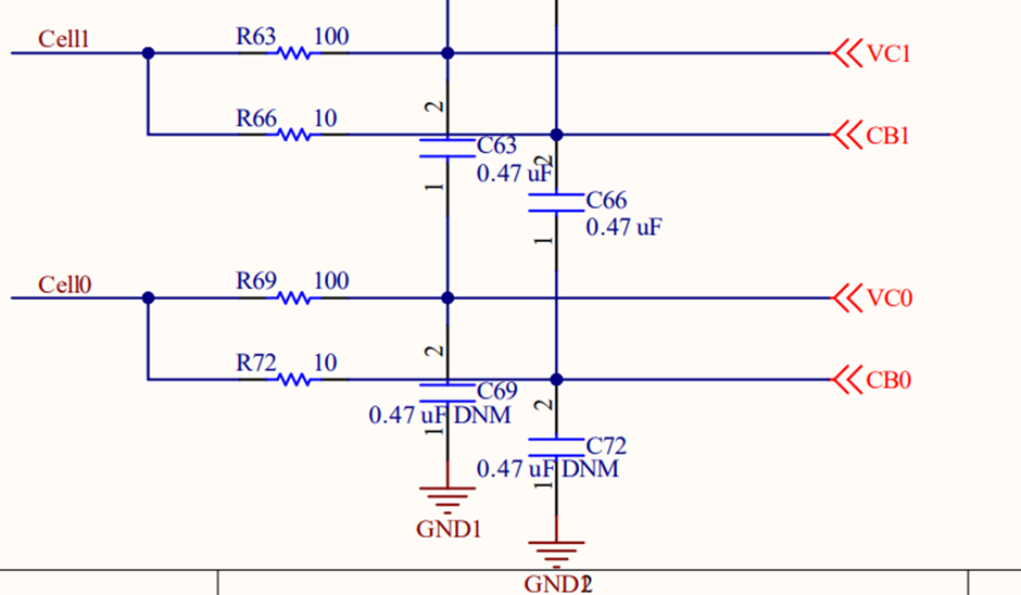
I am working on BQ79656-Q1 IC the problem is When I give 3V only to 16th (VS16) cell then the 16th cell reads 2.4 2.3 like that

but when i connect pack of 16 cell to VS1 TO VS16 than VS1 to VS15 gives exact reading but 16th cell give 0.02V like that .

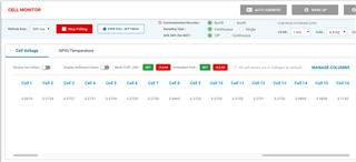
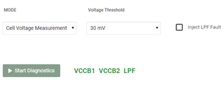
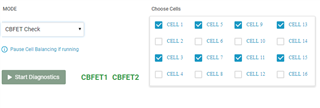
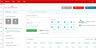
First i try with Bqautoeval after that i use my code but  i am getting same issue in both case.

Thanks.

  • Hi Sudhir,

    Can a schematic please be provided for the cell connections?

    Regards,

    David

  • Hi David 

    Thanks for reply 

    below is my schematic part 

      Thanks.

  • Hi Sudhir,

    The circuit seems correct. With a Multimeter, what is the voltage measured across VC16 to VC15?

    Regards,

    David

  • Hi David,

    Thanks for reply when i check  voltage across VC16 to VC15 with  Multimeter I am getting  +3.2V .

    Thanks 

  • Hi Sudhir,

    Does the BAT voltage read the pack voltage correctly? This can be found in the GUI after you start polling. It can also be read after starting the Main and Aux ADC and then reading registers 0x5B6 and 0x5B7.

    Is num_cell set to 16? This would effect the measurement of cell 16.

    Is VC3 to GND more than 3V? This is required for higher cells to measure properly. 

    Is REFHP to REFHM within datasheet specification? This is a reference for all cells.

    Is the auxiliary adc able to read VC16 correctly? This can be checked by navigating to the diagnostics tab, setting AUX_CELL_SEL to LOCK AUXCELL16, starting the main/aux adc and then seeing what "AUX_CELL" reads.

    Regards,

    David

  • Hi David,

    Thanks for reply 

    I was on leave so I couldn't reply.

    Whatever you said is working as expected

    Can you verify my input circuit for BAT

    ( i am using external power supply for BAT)

    Below is my circuit

    Thanks

  • Hi Sudhir,

    I would refer you to the following section on powering the IC with an external power supply:

    If all cells are 3V, VC16 would be 48V. To read cell 16 properly, the bat pin would need to be more than 48V*0.5 + 2V. Therefore, BAT would need to be supplied by 26V or more.

    Regards,

    David

  • Hi David,

    Thanks for reply 

    I am connecting 16 cells to BQ79656-Q1  and as per the data sheet the minimum input voltage will be (16*3.2V*0.5 + 2V=27.6V)  right now i am giving 29V to BAT but getting issue on Cell 14 cell 15 and cell16 .

    Actual voltage at cell14 cell15 and cell 16 is 3.27.

    But i am getting at cell14=2.3V at cell15 =3.5V and at cell16=3.7V

    Below are the results of BQAUTOeval

    Below are the results of My code

    Thanks

  • Hi Sudhir,

    Is the powerpad of the 616 connected to Ground?

    Regards,

    David

  • Hi David,

    Thanks for reply

    Yes powerpad of the 616 connected to Ground.

    Thanks

  • Hi Sudhir,

    I setup a BQ79616 with 2 power supplies. One power supply powered the resistor ladder from Cell 0 to Cell 16. The other power supply powered VBAT to GND. The 616 was accurate when the two power supplies had the same ground. Is the external power supply sharing the same ground as the capacitors or cells you are using?

    Regards,

    David

  • Hi David,

    Thanks for reply

    NO external power supply not sharing the same ground.

    Please share your OUTCOMES if both ground are not common.

    Thanks

  • Hi Sudhir,

    I applied 42V across the EVM's resistor ladder with one power supply. I then applied 23V from VBAT to GND.

    Here are the main ADC readings when there is no Ground connection between the two supplies:

    Here are the main ADC readings when there is a ground connection between the two supplies:

    It is observed that the non-common ground results are  ~70mV or more away from 42V/16. Cell 1 also reads 3V. Due to differences between a resistor ladder and batteries, my observed results may be different from yours but it is indeed a problem that should be fixed in your BMS.

    Regards,

    David

  • Hi David,

    Thanks for reply 

    I do common both ground but still results is same

    Below is my result snaps.

    again issue with Cell 16 .

    Expected voltage is 2.4 V(through multimeter)

    Getting 3.12V 

    Thanks.

  • Hi Sudhir,

    Does the BQ79616 report any faults in the fault registers? The goal would be to find any errors in FAULT_SYS or FAULT_PWR1, 2, 3

    A second test is to run the diagnostics. These would be to check if there are any wiring faults. There would be three diagnostics to run in the "Diagnostics" tab:

    1. Cell voltage measurement check. Set Voltage threshold to 30mV and see if any errors occur in the VCCB1 or VCCB2 register. If there are VCCB fails then this can be looked at in more detail in the fault registers tab.

    2. CB OW check. Run with the below settings. any faults can be looked at in the fault registers tab.

    3. CBFET check. Run with odd cells and then switch to running with even cells. 

    To eliminate the external power supply as the issue, could you disconnect the external power supply and connect cell 16 to the line that provides power to the BAT resistor and Rnpn resistor? This way cell 16 is powering the BQ79616. If the issue is still observed, then the issue would not be the external power supply.

    Regards,

    David

  • Hi David,

    Thanks for reply

    Below are the results

    (1) Cell voltage measurement check.

    (2)CB OW check.

    (3) CBFET check

    Fault

    (To eliminate the external power supply as the issue, could you disconnect the external power supply and connect cell 16 to the line that provides power to the BAT resistor and Rnpn resistor? This way cell 16 is powering the BQ79616. If the issue is still observed, then the issue would not be the external power supply.)

    Reply- I did not do this test i do this on Monday.

    Thanks

  • Hi David,

    I connect cell 16 to the line that provides power to the BAT resistor and Rnpn resistor 

    This time I am getting issue on cell 15 reading    (cell 15 reading is -3.2V ,through multimeter voltage is 2.4V)

    Cell 16 is giving correct reading.

    Thanks

  • Hi Sudhir, 

    Cell voltage measurement and CB OW is failing in the top cells (9-16). This typically indicates a wiring problem. After performing the cell voltage measurement check, please check the FAULT_COMP_VCCB1 register. This will display which cell is having the issue. 

    Once the problematic cell has been determined, Measure the CB pin voltage and the VC pin voltage to determine what pin is not receiving the expected voltage. If the voltage appears as expected, measure cell n+1 and cell n-1 to determine if there is an issue with the connection above or below that cell.

    Regards,

    David Ray

  • Hi David,

    Thanks for reply and support,

    My board is working fine up after cleanup and reconnect all the setup.

    Thanks.