This thread has been locked.

If you have a related question, please click the "Ask a related question" button in the top right corner. The newly created question will be automatically linked to this question.

UCC25640EVM-020: UCC256404 optocoupler FB pin source current

Part Number: UCC25640EVM-020
Other Parts Discussed in Thread: UCC256404, UCC256402, TLV431

Tool/software:

Hi TI team

In UCC25640EVM-020 VO618A optocoupler is used. 

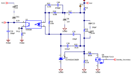
As per the design the opto LED current is (12V-1.2V)/9.09Kohm = 1.18mA. The CTR of VO618A is 50% to 600% as per the datasheet. 

Which will give collector current of  0.594mA to 7.12mA. But as per the datasheet of UCC256404  it says FB  pin can source only 85uA maximum. where does the remaining current will be sourced from .

Please clarify if my understanding is wrong. 

Regards

Rahamadullah

  • Hello,

    Your inquiry is under review and I will get back to you shortly.

    Regards,

  • Hello,

    The opto feedback works a little differently than you think.   

    First, let me try to explain how the UCC256402 device controls the oscillator frequency.

    To control the oscillator frequency requires adjusting the current out of the FB pin (IFB) from 0 to 82 uA.

    Due to variation in the internal current source, the FB pin may have to be adjusted from 0 to 91 uA to get the full oscillator range.


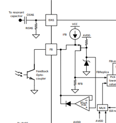
    To try to get a better understanding of how the control works lets look at the following block diagram.  IFB is an internal current source of 82 uA.  When the opto collector sinks all of the current from IFB there is no voltage across RFB, since there is no current going through it.  At this point the LLC controller is operating at the maximum switching frequency and the gain of the LLC power stage is at its lowest.  When the opto draws no current the 82 uA from IFB goes through RFB.  This causes the controller to operate at its minimum frequency and the LLC power stage gain is at its maximum.  So the voltage across RFB controls the switching frequency of the LLC to adjust the power stage gain of the LLC.     

    The opto feedback will adjust the opto diode current to control and adjust the current coming out of the FB pin.  This in turn controls the LLC switching frequency to control the power stage gain and maintain the output voltage.   This is not a fixed current and will vary based on the OPTO NCTR.  Please note that this circuit cannot draw more current through the opto collector current than IFB source can provide.

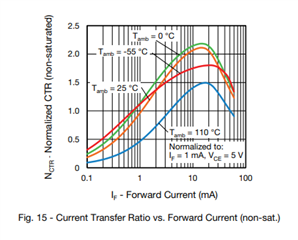
    Below is graph from the VO618 data sheet that shows how NCTR varies with ambient temperature and bias current.  Depending on the NCTR the current and voltage across R18 will vary.  For example if you had an NCTR of 0.5 and it required 50 uA of current drawn out of the FB pin.  This would require the diode current of the opto to be 100 uA.  The TLV431 would adjust the voltage across R18 to limit the current to 100 uA.

    If the NCTR was 6 or 600 %.  To maintain 50 uA of current coming out of the FB pin would require 300 uA of opto diode current.  If this is the characteristics of the opto you are using the TLV431 would then again adjust the voltage across R18 to achieve this current.

    This opto feedback configuration does not use a fixed bias current through the opto.  The opto current is adjusted based on the oscillator frequency requirements to maintain the output voltage.

    Thank you for interest in Texas Instruments (TI) products.  If you have a related question, please click the "Ask a related question" button in the top right corner. The newly created question will be automatically linked to this question.

    Regards,