Tool/software:
I had a similar question to the post below.
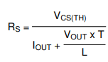
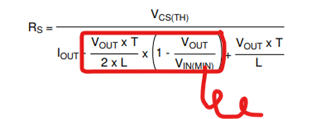
It is not clear why the current sense resistor would be calculated from Vcs/(Iout + (Vout * T) / L).
I am solving for the average current limit of my design using the LM5116 with a given sense resistor, so I am left with this equation: Iout = Vcs/Rs - ((Vout*T)/L). The actual current limit I measure is pretty close to this equation, but I do not see why Vout * T / L is correct. I could see subtracting the inductor ripple current, since the inductor ripple current will have an average current value + the ripple current. But the equation of Vout * T / L is not accurate. During the off time of the high-side FET, the equation is Vout *Toff / L, not the whole period T.
Can someone explain why this equation is correct?
LM5116: LM5116 equation 35 & 37 - Power management forum - Power management - TI E2E support forums

 =======>