This thread has been locked.

If you have a related question, please click the "Ask a related question" button in the top right corner. The newly created question will be automatically linked to this question.

TPS23754: UVLO threshold of TPS23754

Part Number: TPS23754
Other Parts Discussed in Thread: TPS23756, ,

Tool/software:

Hi Team

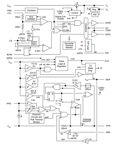
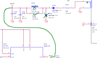
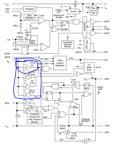
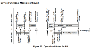
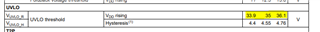
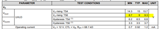
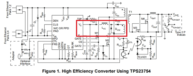
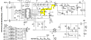
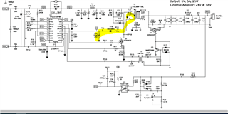
Customer found the DS descript the UVLO threshold is about 10V, but it will turn down when Vcc drop to 20V. Can you help to comment is there misuderstanding? the attachment is their schematic. 

 WAPI-5018-O3-2405 _ 13_POE.pdf

  • Hi Harry,

    I assume you are talking about TPS23756 instead of TPS23754.

    TPS23756 has ~9V UVLO at VC. VC also has a max operation voltage (recommended operating conditions) as 18V. So it is needed to make VC 9 - 18V during operating. And normally 12 - 16 V is more common. 

    For the schematic,

    1. Could you share the T701 transformer datasheet?

    2. Could you extract the VC-RTN waveform?

    3. You may try to DNP D704 and L702. Populate L703 and try again.

    Best regards,

    Diang

  • Hi Diang

    Thanks for your response. and sorry for misleading. yes, it is TPS23756, and what I mean is VDD's UVLO which is shown as the following picture. I am not sure if we misunderstanding this block diagram?

  • Hi Harry,

    Thanks for your detailed description. These cycled voltage comparators are for the detection (VDD-VSS = 2.7 - 10.1 V) and classification (VDD-VSS = 14.5 - 20.5 V) status. 5&4 V could be related to hotswap disable threshold.

    TPS23756 integrates the PD CTL which has UVLO ~35V, and PWM CTL which has UVLO ~9V. Though there are other UVLOs, these two are most commonly referred  

    Besides, I would recommend you to DNP D704 and L702. And populate L703 (0-Ohm)

    Best regards,
    Diang

  • Hi Diang

    Thanks for clarification. I have a question that the typical block diagram in DS shown as following, it integrates D74 and L702. Could I understand why you recommend DNP these two devices?

  • Hi Harry,

    Thanks for your follow-ups. I will get back to you in 3 business days. 

    Best regards,

    Diang

  • Hi Harry,

    The AUX circuit will be different for flyback converter and forward converter. The DS is based on forward converter. And your schematic is flyback. 

    TPS23754EVM-383 is forward reference design 

    TPS23754EVM-420 is flyback reference design