Other Parts Discussed in Thread: BQ25792, , BQ25792EVM, TPS25750
Tool/software:
Hi,
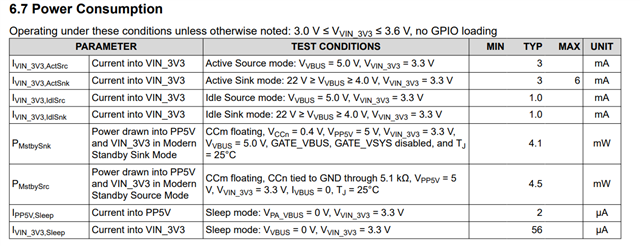
May I know the TPS25751D standby current in DRP role? The standyby power consumption can I reference to Ipp5V,sleep(2uA) + Ivin_3V3,Sleep(56uA) = 5*2 + 3.3*56 = 10 + 184.8 = 194.8uW?
Since our device have integrate battery, we concern about the standby power to make sure TPS25751 won't take more power consumption in standby more. Thanks!
Jeff