This thread has been locked.

If you have a related question, please click the "Ask a related question" button in the top right corner. The newly created question will be automatically linked to this question.

TPSM33625: Feedback Resistor Selection

Part Number: TPSM33625

Tool/software:

There're few questions here.

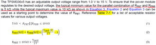
1. What's the reason that the equation needs to follow 5K < Rfbt//Rfbb <= 10K ?

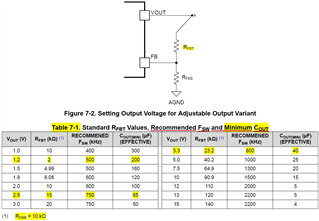
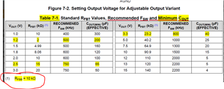
2. In application, the Vout = 1.2V, Rfbb=10K and Rfbt=2K are suggested in table 7-1. however if 1.6K is selected for Rfbt, any side impact?

3. In the table 7-1, the 200uF is suggested to use for given Vout=1.2V and Fsw. but in reality there's a pcb size constriain. it looks 200uF is too big size. Is there related equation or curve about this Cout determine?

4. Customer would like to design as below I/O spec with TPSM33625. How to select and design the Fsw and Cout? This is for the AC inverter application. 

Vin = 5V

3.3V/300mA

1.2V/200mA

1.3V/450mA

2.5V/150mA

  • Hi Brian,

    1. TPSM33625 devices detect the feedback resistor values to determine if they need to be in fixed VOUT mode or adjustable VOUT mode. Equation 1 being satisfied helps the device determine that optimally.

    2. Hmm for Your customer it may be better to choose 50KOhm for Rfbt and 10KOhm for Rfbb since that would have Equation 1 equal 8.333KOhm.

    3. The way the math works out, the smaller the VOUT that's needed the more COUT you need. It increases at a high rate because the VOUT term in on the denominator.

    It may be worth to have your customer test their solution on an EVM to see if it's feasable

    COUT equation:

    https://www.ti.com/lit/an/slva477b/slva477b.pdf

    EVM:

    https://www.ti.com/tool/TPSM33625EVM

    4. It's ok to use the recommended FSW and COUT from the chart you posted. Again for the small VOUT values, the customer should qualify their solution on an EVM if they want to have lower than recommended COUT.

    Thanks,

    Andrew

  • For the question 1, what we would like to know why table 7-1(When) is not follow up the equation of the  5K < Rfbt//Rfbb <= 10K

    For example in 7-1, when VOUT=1.2V, RFBB=10K and RFBT=2K. The RFBB//RFBT = 1.67K Ohm. That is out of the range in the d/s, isn't? And also, in the Webench, it's also out of the recommendation range. Could you help to clarify it?

    Regards

    Brian

  • Could you help on this inquiry! Very thanks.

  • Hi Brian,

    For the conditions listed in the DS, we wanted a constant RFBB of 10Kohm. The table lists a large range of output voltages 1.0V - 15V. I don't think there's a single RFBB value that can satisfy the Rfbt//Rfbb <= 10K if RFBB is a constant 10k.

     '
    We did valdidate that the values listed in the DS do work, however if you plan on deviating from the DS, then TI recommends that you follow Rfbt//Rfbb <= 10K so that your device operates as expected.