This thread has been locked.

If you have a related question, please click the "Ask a related question" button in the top right corner. The newly created question will be automatically linked to this question.

LM3409: Heating Issue found on the LED driver

Part Number: LM3409

Tool/software:

Hi TI team,

The part number of the LED driver is LM3409MYX/NOPB.

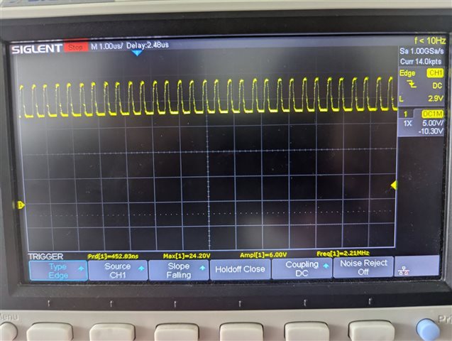
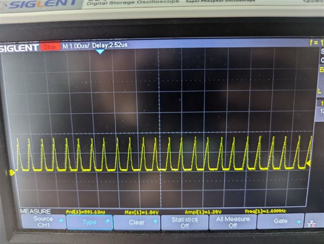
We observed a heating of more than 60°C while connecting the LED load. Also we observed slight heating even without connecting any load.

Attaching the schematics of LED driver for reference.

Kindly check it and may i know the reason for the heating of this board

 Light sensor Board.SchDoc

  • Hi Alan,

    Please give us some time to review it, additionally, what is your load condition? Thanks!

    BR,

    Hailee.

  • Hi Hailee,

    Currently we have connected a LED load of arount 300mA.

    Our actual load will consume a current of 500mA.

    Another observation is like If we have connected the load of 500mA, the temperature on the LED driver side will shoot up to 100°C

  • What is input, output voltage, LED load? Can you provide BOM list? 

    Also, thermal dissipation is highly related PCB layout, heat sinker and system design. 

    When you observe a heating of more than 60°C, which ones are hottest?  

    Have you seen any abnormal operation? You may share test waveform when it is hot. 

    You can roughly calculate power loss for each component and see if there is challenge for thermal dissipation. 

  • Hi Xiaoguang,

    The input voltage is 24V

    Expected output voltage is 20.5V

    The hottest part is the LED driver not the MOSFET

  • It shouldn't be so hot. 

    Can you capture waveforms on board? 

    I'd like to check PGATE, SW node, COFF voltages and inductor current when it is hot. 

  • Hi Xiaoguang,

    Please find the attached data captured during different conditions

    Load Current Gate Voltage IADJ Coff SW OUT
    Condition 1 120mA 20.65V 0 750mV 16V
    Condition 2 230mA 19.88V 608mV 580mV 16.93V
    Condition 3 358mA 19.36V 999mV 480mV 17.8V

    Attaching the scopshot of PGATE signal while connecting load

    Also Attaching the scopshot of COFF signal

    One more observation is even if the voltage across is IADJ pin is 0V, We can observe a 30-40% of LED brightness.

    What can be the reasons for that?

  • Is your design different from the schematic? 

    The test frequency is 2.21Mhz, while the design should be around 500khz with parameters in schematic. Please reduce frequency and try, this will reduce drive loss and switching loss. 

    Please also capture SW node voltage and inductor current besides Pgate. Please have them in same figure together with at least 2 channels. 

    For IADJ pin is 0V, could you also test the waveform of IADJ,  SW node voltage and inductor current together? I think it might due to the minimum on time.