This thread has been locked.

If you have a related question, please click the "Ask a related question" button in the top right corner. The newly created question will be automatically linked to this question.

LM5123-Q1: BYPASS OPERATION DROP

Part Number: LM5123-Q1
Other Parts Discussed in Thread: LM5122

Tool/software:

Good Morning

We are testing a board where we used a LM5123-Q1 to boost UP an input voltage in the range of 9.5V - 16.0V to 11.9V. The input voltage will be, in normal operation, higher than the output boost voltage, so our idea was to use the chip in bypass mode most of the time and use it only when the input voltage drops down. The maximum continuous output current is 3.5A. In this test the enable pin is connected directly to the input voltage with a wire. We added a capacitor 1uF 0805 50V in parallel to C64 to add more capacitance at the bias input.

The schematic is this:

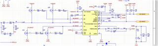
The boost, when the voltage is lower than 11.9V, work correctly as boost, realizing the correct output voltage at different load.

When we rise the input voltage over the output set point, it correctly stop switching and active the charge pump, in order to keep the high side mosfet high. and it correctly does it.

The problem appears when, from a voltage higher than 13V, we decrease linearly the voltage, at around 12.6V, the high side is turned off without any reason.

We checked both VCC and HB-SW voltage, and they are still high in this events; then there are two scenarios:

- if we continue to decrease the input voltage, at around 12.4V the high side is turned on again (with some pulse of switching);

- if we rise again the voltage, the high side is turned on again at around 13.4V;

Do you have any suggest or idea to solve this issue? Are we missing something in the operation of the chip?

Thank you very much in advance for help

Attached also a oscilloscope view: (CH1: high side gate, CH2: output voltage, CH3: VCC, CH4: not connected, all voltages are refer to ground)

  • Hello Harry

    Thank you for your reply. We tried both at no load condition and at around 2.5A output and this effected still the same.

    We didn't try to go change the load during this situation (when the high side is no longer high), but I can try to see if it has some effects.

    Stefano

  • Ok I have tried this situation:

    - input voltage voltage is higher than output setpoint, around 13V and the high side switch is on; decreasing linearly down to 12,6V and the high side turn-off, almost at no load condition;

    - changing the output power, increasing up to more than 2A, the high side switch turns on again;

    - tried to reducing again the voltage, even with high load on (>2 A on the output), the high side switch drops again down;

  • Hello Stefano,

    Thanks for reaching out to us via e2e.

    It seems that my previous reply somehow got messed-up. I am sorry for that.

    As per your description, the LM5123 behaves exactly as described in the datasheet.

    As you can see in the table on page 10, there are thresholds when the bypass mode is entered or left again.
    VOVTH-RISING : Bypass gets entered when the actual output voltage rises above 108% of the commanded output voltage.
    VOVTH-FALLING. Bypass mode gets turned off, when the actual output voltage falls below 105% (100.5% min .. 109% max) of the commanded output voltage.

    So, at around 12.5V, bypass mode gets turned off, although the output voltage is still 5% above the commanded value.
    The high-side FET turns off and there is no switching.

    When the actual output voltage is further falling, the controller will decide to do single pulses with long gaps in-between to keep the output voltage at the expected level.
    In this pulse skipping mode, the energy-packet that is transferred with a single pulse is so high, that it will take a long time until the next one is needed.
    If it was permanently switching, the output voltage would rise too high.

    Please also see figure 8-17 which illustrates what I have described above.

    Best regards
    Harry

  • Hello Harry

    Thank you for your answer and details; but that means that in the range between 105% and 100% the high side will not be on, unless there are some variations in the load or in the input voltage?

    Best regard
    Stefano

  • Hello Stefano,

    This is correct.  

    Best regards

    Harry

  • Hello Harry

    Ok, thank you very much. Do you any suggestion about how to avoid that period where the high side switch is off?
    Thank you again and best regards

    Stefano

  • Hello Stefano,

    I am sorry, the LM5123 has been designed like that. There is no way around it.

    The LM5122 does not have these different thresholds.
    But it has other limitations and restrictions.
    - To be able to use bypass mode, the output voltage has to be above 9V, ideally even 12V or above.

    - When you want to use bypass, the controller has to be set to FPWM mode.
    This way there is no pulse skipping and it will either permanently shift the energy back and forth (in Forced PWM mode, which is pretty unefficient) or go into bypass

    - It can happen tat it will oscillate in and out of bypass (no hysteresis like in case of the LM5123)

    - It cannot really start-up directly into bypass mode, so you will need to add some external components to overcome this behavior.
    Analysis and Solution of the LM5122 Bypass Function Loss
    www.ti.com/.../snvaaa5

    By the way, the circuitry in this application note will not help to change the behavior of the LM5123.

    I would propose that you get an EVM of the LM5122, add the components described in the application note and give it a try.

    Best regards
    Harry