This thread has been locked.

If you have a related question, please click the "Ask a related question" button in the top right corner. The newly created question will be automatically linked to this question.

BQ76952: BQ76952

Part Number: BQ76952


Tool/software:

HI!!

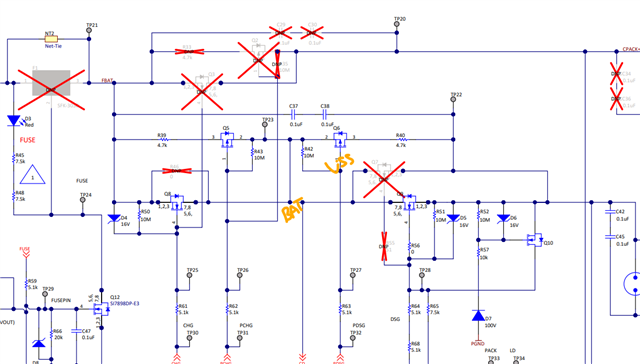
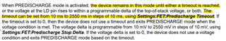
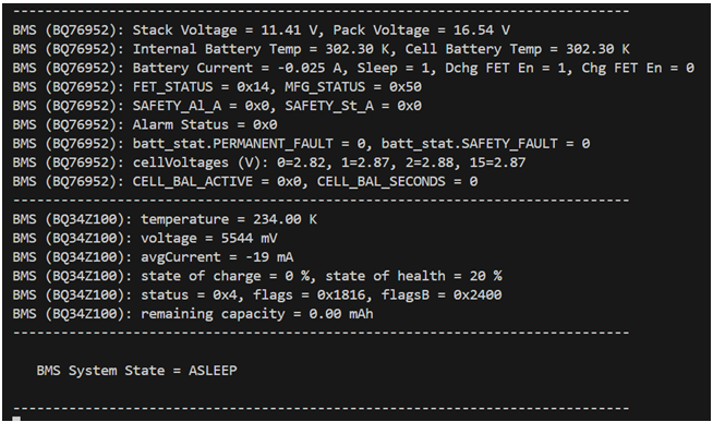
We are having an issue with charger detection while in sleep mode. Our BQ76952 device is transitioning to sleep mode automatically when the current is sufficiently low, which is the desired behavior. And when the device transitions to sleep mode, the CHG FET is automatically disabled, which seems fine. Then, when a charger is attached there is a noticeable PACK-TOS delta, but the device isn't waking up. See below screenshot in which the stack voltage is 11.41V, the pack voltage is 16.54V and the device remains asleep. We are writing 20 to the 0x9250 data memory register which is in units of 10mV, which means that the device should detect a charger if the PACK-TOS delta is greater than 200mV. But the device isn't waking up. The FET status register is reading 0x14, the 0x0057 MFG Status register is reading 0x50. There are no active faults. Are there other conditions that must be met to allow the device to wake up when a charger is detected via the PACK-TOS delta?

Thanks!

John

  • Hi John,

    Yes one more requirement must be met before the device will wake up. Can you check the Power:Sleep:Sleep Charger Voltage Threshold setting?

    Best regards,

    Thomas Rainey

  • Hi Thomas,

    We tried another board and it worked as well as the remaining boards so seems like we have a bad board. Sorry for the fire!! But I do have 2 more questions:

    1. When the device goes to sleep and the FETS turn off, the PACK voltage seems to float and rise. If it floats up randomly, it will wake up the device, often very quickly because the BQ76952 will detect a PACK-TOS differential and think there is a charger. THen it will go back to sleep and wake up, and go back to sleep, in a vicious cycle. To prevent this, I've clipped a multimeter to the PACK+/- terminals. With a multimeter across the PACK pins, it keeps the PACK pins from floating. This keeps the device asleep, which is good, until a real charger is connected and a real delta is observed on the PACK terminals. What is going on here?

    2. Pre-discharge FETS. From my understanding, the pre-discharge FETs are to charge up a capacitive load to bring the voltage up to a point where you move into a better location on the SOA chart of the main FETs. In other words, reduce your Vds so you can handle more current for longer periods of time when you turn your main FETs on.  Maybe I'm wrong?  But in the case of a purely resistive load (let's say a heater) with a very small resistance, then with a 4.7K pre-discharge resistor and a very small resistive load, then the voltage will never exceed the turn on threshold for the FETS. Maybe I'm missing something?

    Thanks so much!

    John

  • Hello John,

    1. PACK should be pulled low internally to avoid this: 

    2. You are correct. However when a purely resistive load is attached the it will still turn on the PFET. The PDSG pin is pulled to VSS and your source voltage is BAT allowing the PFET to be on.


    Best regards,

    Thomas Rainey

  • Hi Thomas,

    Your answer for question one is not clear to me. Is that a circuit you recommend? Why is in not in the eval board (or maybe I missed it?) nor recommended when TI review my schematic? 

    As for question #2, I guess I wasn't clear on my question.  There is a threshold register for VPACK and when it exceeds a certain voltage it allows the main FET's to be on.  For a capacitive load, if you didn't pre-discharge, if the main FETs were to turn on, the caps would be charging (lots of inrush) and the Vds would be very high and you might violate the SOA of the FET. This is how I understand the why there is PDSG.  But if you have a resistive load, that threshold will never be met because there is a 4.7K series resistor in line with the resistive load which is going to be much less than 4.7K and therefore the PACK+ voltage will be very low as most of the voltage will drop across the 4.7K resistor and therefore the threshold to turn on the main FETS will not be turned on.  Maybe I'm not fully understanding how this will work for resistive and capacitive loads?

    Thanks!!

    John

  • Hi John,

    1. That is internal to the part not external. It is in the Pin Equivalent Diagrams for the BQ76952, BQ76942, and BQ769142  applications report.

    2. You are understanding correctly. But predischarge also has a timeout function that can be unutilized if that voltage on the LD pin is never met.

    Best regards,

    Thomas Rainey

  • Hi Thomas,

    Making sense now! Thanks. One last question.  I looked for the CONTROL bit with no luck. How is this set/reset? Is there a bit in a register?

    Thanks again! Most appreciated.

    John

  • Hi John,

    Yea sorry for the confusing. The control is a general label. Multiple functions can use it, so there is no register. It is sometimes in the description of the specific functions.

    Best regards,

    Thomas Rainey