This thread has been locked.

If you have a related question, please click the "Ask a related question" button in the top right corner. The newly created question will be automatically linked to this question.

LM5176-Q1: Stop working after 10-15 minutes

Part Number: LM5176-Q1
Other Parts Discussed in Thread: LM5176

Tool/software:

Hello,

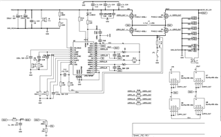
I am designing DC-DC buck-boost converter using LM5176.

Specification:

Input: 9V to 36V

Output: 12V/6A

Switching frequency: 280 kHz

---------------------------------------------------------------------------------

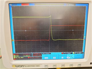
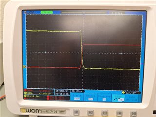
Yellow - High side switch

Red - Low side switch (Inverted)

As seen in picture I am getting almost no deadtime between high side and low side switch operation.

Question 1: How I can add deadtime?

---------------------------------------------------------------

Initially for 10-15 minutes it works fine then suddenly it stops working. after 1 or 1.5 hours It works for the same. After it stop working, I checked Vcc and it is completely zero, and EN pin voltage is around 0.7V (Input voltage 24V is applied), from datasheet it shows undervoltage cutoff. After 5-10 minutes, Vcc restored to 7V and EN pin voltage tries to rise but due to some issue it can't be restored. EN pin continuously triggring like high-low-high-low. IC not getting hot so I don't think the issue is thermal cutoff. 

Question 2: What could be the possible reason for acting as mentioned above? and for that what would be the solution?

Thank you.

  • Hi,

    thank you for using the E2E forum.

    1. as you can see there is a dead time of some 10ns which is what should be there. So for me this looks OK.

    2. have you checked the temperature of the circuit? What is the hottest spot on the PCB / Components short before the shut down?

    Best regards,

     Stefan

  • Hello @

    Thank you for your response.

    1. I think as shown in picture there are pulses overlapping for minimum 20ns, means no deadtime. By the way I increased the gate resistor with antiparallel diode that helps me little bit.

    2. For temperature measurement I have only laser based temperature gun (without camera) that just give me temperature value. I measured the hottest spot at high side mosfet around 65 degree Celsius and SW junction around 60 degree Celsius and IC temperature was less than 40 degree Celsius.

    The room temperature is around 24 degree Celsius so it cools down quickly. 

    I think I have to check replacing 1 by 1 components and have to check. Can you give your guess for which component probability of damaged is highest?

    I also prepared to other boards and both of them worked as expected. Just because of thermal management issue I couldn't put for long run taste as temperature reaches just above 70 degree Celsius.

  • Hi,

    With a horizontal scale of 100ns/div this dead time is hard to see.

    I missed that you have placed gate resistors as this are moved to the lower right boarder. Can you let me know which values you are using here?

    If gate resistors are used the internal circuit to ensure dead time is not violated can be interfeared. So if gate resistors are used this should be less then 5Ohm but also depends an the Gate charge.

    Best regards,

     Stefan