Part Number: TPSF12C3-Q1
Tool/software:
Dear TI experts,
I am using PSpice for TI and the simulation models provided about the TPSF12C3-Q1. I have some questions about the transient model then one on the AC model.
Transient model :
1 – Do we have to add our load connected the “Line_OUT’” terminals ?
At the end of my power lines, there is a rectifier then an inverter. I can add the rectifier to the diagram, and I have the current waveform from the inverter.
2 – In the initial model, the supplies are 3 pulse generators with high dv/dt impulses. Do they stand for differential mode source ? In my study case, I have 3 sinus generators, could I add them or it doesn’t matter because we only regard the noise ?
3 – Does Vsw stands for common mode source ?
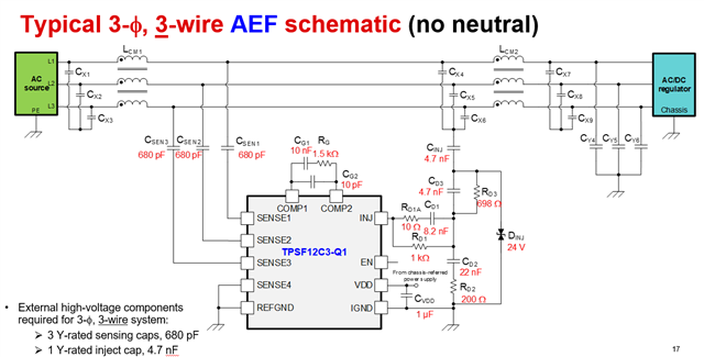
4 – Why are Cx1, Cx2 and Cx3 connected to N_artificial ?
5 – I would like to compare the CM noise with and without the active filter. Is it enough to put EN at ground level to avoid every IC’s effects ?
6 – In order to measure CM and DM noise, do we have to add a LISN model on each line ?
AC model :
7 – Could you confirm that if we regard gain and phase on inductance L24 terminals, as it is written on the diagram, we should find the same gain and phase as the excel spreadsheet calculator ?
I apologize if some of my questions could be obvious, but I am not an expert in this field.
Regards,