This thread has been locked.

If you have a related question, please click the "Ask a related question" button in the top right corner. The newly created question will be automatically linked to this question.

TPS61165-Q1: TPS61165EVM-283 : Difficulties with the software and device configuration.

Part Number: TPS61165-Q1
Other Parts Discussed in Thread: TPS61165, USB-TO-GPIO2

Tool/software:

Hi all

I recently purchased the TPS61165EVM-283 and I'm encountering some difficulties with the software and device configuration.

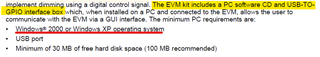
There was not a software CD included in the EVM KIT. When I first tried to download the GUI, I followed the link in the user guide but it showed an error message (slvc422a). I thought maybe because my device has a Windows 10 version while the  software is only compatible with older versions of operating systems windows 2000 or windows XP 

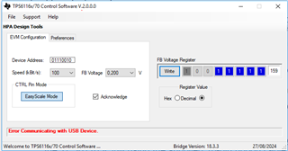
I managed to find a version that I can install, TPS6116x/70 Controller Softwarebut I'm uncertain if it's correct as I'm still experiencing error messages and cannot accurately set the feedback voltage.

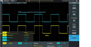
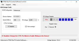
The software indicates the IC is disabled, even though it's powered and consuming current, and in order to start writing on the device the "CTRL" Pin mode should be set high (I'm not using PWM Dimming via CTRL pin) (see results in image1).

=> I have powered it up using 5V @ 1A as limit current of the power supply.

  • Image 1: 

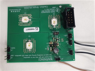
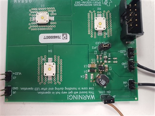
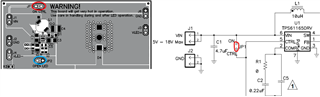
I've tried manipulating the CTRL pin as per the schematic but without success - It said that the CTRL signal needs to be high, so I shunted it with the the "on" pin side, to be set with the power voltage 5V (indicated with the red circle in the schematic and in the assembly sch. -  see image 2)

In both casses, when the "CTRL" pin in High or Low, the SW tool could not configurate the VFB.

  • Image 2: 

I'm hoping you can provide some guidance on these issues.

Thank you,

Nesrine

  • Hi Nesrine,

    If you want to use the GUI to control TPS61165, you should remove the jumper on JP1.

    BR

    Patrick

  • Hello Patrick, 

    I am Anubha, FAE supporting this customer. 

    They have tried removing the JP1 jumper but still issues are seen. 

    Can you please try to look into this on a priority basis ? My customer has not been able to advance since 3 weeks. 

    Thanks for your support!

    Best regards,

    Anubha

  • Hi Anubha,

    OK, let me setup with our EVM and give you the reference later.

    BR

    Patrick

  • Hi Anubha,

    I can use the GUI to control TPS61165 following below steps:

    1. Remove jumper on JP1

    2. Supply EVM with 5V input voltage

    3. Open the GUI, switch the "CTRL Pin Mode" to Easy Scale mode

    4. Choose a FB voltage, and make sure you click the "Write" button to send data

    BR

    Patrick

  • As a brief overview, I’m currently using a TPS61165EVM-283 (HPA283 REV. C -2009) with USB-TO-GPIO2 adapter 2006. Despite various attempts to modify the CTRL pin state, the acknowledgment state is not being reached.

    These are the conditions that I applied :

    Scenario ① : Followed the exact same instructions that you recommended :

    1. Removed the jumper of JP1
    2. Connected the EVM to the PC via the USB-TO-GPIO adapter
    3. Supplied the EVM input voltage with 5V
    4. Opened the GUI, switched the "CTRL Pin Mode" to Easy Scale mode
    5. Chose 200mV as FB voltage than clicked on “Write” Button.

    => Still the acknowledgement from IC (driver) did not occur neither did the on-board LEDs light up.

    Scenario : Analog dimming via PWM signal

    1. Removed the jumper of JP1
    2. Connected the EVM to the PC via the USB-TO-GPIO adapter
    3. Supplied the EVM input voltage with 5V
    4. Connected a Function Generator to the CTRL side of the JP1

    Please note that the Function Generator generates a PWM signal with these specifications : Amplitude ≈ 4V and frequency (PWM) ≈ 7.5 KHz [see picture below]

    => This was the results from the GUI plus no LEDs dimming had occurred even after providing the CTRL pin PWM signal.

    I can’t really identify the root cause of this behavior. I’ll wait for your prompt response.

    Thanks,

  • Hi Nesrine,

    Seems this issue is related to your adapter, have you updated its firmware? You will find the "Firmware Flashing Utility.exe" in the folder where you downloaded the GUI. Connect the USB adapter and double click the .exe.

    BR

    Patrick

  • Hi Patrick,

    Yes, indeed I've updated the firmware for the adapter. But just to make sure that I'm using the right version could you attach the link for the most recent firmware of the adapter.

    Best Regards

  • Hi Nesrine,

    So the LED can't be light up? Is the JP2 jumper installed on your board?

    BR

    Patrick

  • Hi Patrick, 

    I've checked their functioning with a multimeter and they're are not damaged. And yes, the jumper on JP2 is installed while the JP1 jumper is removed on the board when the test is conducted.

    BR

  • Hi Nesrine,

    If JP1 jumper is added (connect CTRL to VIN), will the LEDs still not light up?

    BR

    Patrick

  • Hello Patrick,

    Yes, indeed I've already tried this option, and LEDs still wouln't illuminate.

    BR

  • Hi Nesrine,

    That's strange, when you power on the IC, could you please measure the voltage on VOUT? Is it equal to VIN? If your hardware connection is correct but there still no output, I suspect the IC on EVM might be broken.

    BR

    Patrick

  • Hi everyone,

    I’m collaborating with Nesrine on the same project and recently conducted the test requested by . I discovered that the output voltage matches the input voltage.

    Additionally, I replaced the IC and measured the FB voltage before updating the feedback register. Initially, the FB voltage was 0.05V, but after updating the code, it changed to 1.9V with a 5V power supply.
    LEDs still not light up !

    Best regards,

    Ayoub

  • Hi Ayoub,

    Are you using all the 3 LEDs on the board? If Vout equals to Vin after you power on the device, that means the device is not working (not boosting voltage). The normal output voltage should be ~9.5V.

    Could you please take a photo of the EVM with your jumpers' setup? Let me check if there is anything wrong.

    BR

    Patrick

  • Hello Patrick,

    Is it normal for the FB voltage to be around 1.9V?

    1st Test:

    I removed JP1 and tried to control the IC with an external PWM signal, but nothing happened.

    2nd Test:

    I mounted the JP1 jumper, but it still didn’t work.

    Note: I’ve changed the IC several times, but the problem persists. I’ve measured all the surrounding components, and they all seem to be working fine.

  • Hi Ayoub,

    Seems you soldered the SOT-23 package? The EVM should be soldered with WSON package, and they are not pin to pin capable.

    BR

    Patrick

  • Hello Patrick,

    The component is soldered backwards, so the pinout of the WSON and the SOT should be compatible (without contacting the thermal pad underneath). Both have the same features as far as I know, so this shouldn’t be an issue. As shown in the image, if we mirror the IC, it should be pin-to-pin compatible.

  • Hi Ayoub,

    If you solder the IC backwards, will it light up the LEDs? And you can try to control it with the GUI again.

    BR

    Patrick