This thread has been locked.

If you have a related question, please click the "Ask a related question" button in the top right corner. The newly created question will be automatically linked to this question.

LP5810: LED is turned on with very low brightness in spite of MC=0h and DC=00h when VCC=3.3V, VLED=5V.

Part Number: LP5810

Tool/software:

Hello guys,

One of my customers is evaluating LP5810 for their next products.

In the evaluation, they found LED is turned on with very low brightness in spite of MC=0h and DC=00h when VCC=3.3V, VLED=5V. Also their controller signal H/L level are 3.3V/0V.
Same phenomenon is observed just after LP5810 powered up. But the phenomenon was disappeared when VCC=VLED=5V.
At this moment, they have the following questions. Could you please give me your reply?

Q1.
This phenomenon is a normal operation of LP5810?

Q2. 
Is the condition, VCC < VLED not allowed?

Q3. 
Is there any way to turned off all LED completely under VCC=3.3V、VLED=5V condition?

Q4.
This is a question not regarding to the phenomenon above,
 Can their controller access to LP5810 via I2C when LP5810 VCC=5V and their controller signal H/L level are 3.3V/0V?

Your reply would be much appreciated.

Best regards,
Kazuya.

  • Hi Kazuya,

    Our expert is currently out of office. He will reply to you next Monday. Thanks for your understanding. 

    Best Regards,

    Steven

  • Hi Steven,

    Thank you very much for your reply.

    I'm looking forward to receiving your team member reply.

    Thank you again and best regards,
    Kazuya.

  • Hi Kazuya,

    Sorry for late reply due to the sick leave before, I will test it on EVM today and reply you by today. Thanks for your patience.

    BR, Jared

  • Hi Kazuya,

    I didn't see such behavior on my EVM, can you please help to show me your schematic?

    Here is my email address: jared-zhou@ti.com

    BR, Jared

  • Hi Jared,

    Thank you very much for your checking on EVM.

    I will ask them to give us their schematic and I will email it to you as soon as I get it.

    At this moment, I have several questions about LP5810.
    Could you please give me your reply.

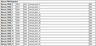
    Q1. Does PWM dimming registers have any default value?

    Q2. Just after LP5810 powered on, PWM dimming data is reset to zero?

    Q3. Is there leak current spec of OUTx(X=0~3) when DC data and PWM dimming data are zero? Or do you test the leak current in production test?

    Q4. I could understand you didn't see similar phenomenon with the customer on EVM.
      The device internal circuit wise, even if the DC data is set to "00h", isn't it possible that the variations of internal ope-amp offset or mirror circuit miss-matching cause leakage current?

    Q5. Is OUTx leak current not flown when OUTx voltage is higher than VCC? Also is this condition allowed?

    Q6. This is a question not regarding to the phenomenon above,
          Can their controller access to LP5810 via I2C when LP5810 VCC=5V and their controller signal H/L level are 3.3V/0V?

    Thank you again and best regards,
    Kazuya.

  • Hi Kazuya,

    Please refer my comments below:

    1. Yes, you can find it in the detail register map and here is the link. The default value of PWM is 0x00 for PWM dimming register.

    2. Yes, after powered on every time, the PWM dimming data will be reset to default value.

    3. I think there might be a little leakage current when DC and PWM data are zero, but I don't think it can light the LEDs. I will test the leakage current on EVM later.

    4. I understand that there may be differences in each device, but I think that is very unlikely.

    5. Yes, I think it won't and LP5810 can allow this condition VLED > VCC.

    6. Yes, I think it's no problem since the I2C pullup is decided by externally pullup and the device can be controller by MCU once the VCC is higher than UVLO.

    Please let me know if you have any questions.

    BR, Jared

  • Hi Jared,

    Thank you very much for your supports.

    I got the customer schematic and a few additional information.
    I emailed these to you just now.

    Could you please take a look and please give me your reply?

    Thank you again and best regards,
    Kazuya.  

  • Hi Kazuya,

    Ok, I will reply to you later on email and let's discuss about this problem on email.

     Btw, I test the leakage current when the PWM&DC=0 and I can't measure the current since it's too small.

    BR, Jared