This thread has been locked.

If you have a related question, please click the "Ask a related question" button in the top right corner. The newly created question will be automatically linked to this question.

TPS23753: TPS23753 transformer matching parameters

Part Number: TPS23753

Tool/software:

Hi all,

Could you please provide the recommended parameters for this transformer that matches TPS23753? When the customer was testing the temperature rise of the IP phone, he found that the temperature was very high and the transformer was heating up seriously. The conversion efficiency of the entire POE module was only about 60%. So he would like you to provide the recommended parameters to see if there is a problem with the transformer selection, or if you have any suggestions to improve the power conversion efficiency, thank you very much.

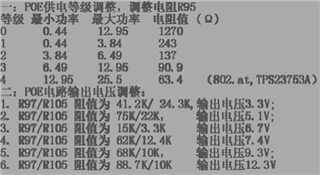
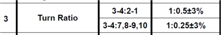
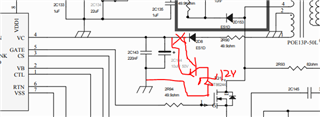
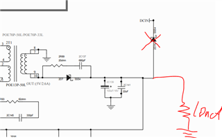
The following is the schematic diagram and the matching transformer.

1_UM7715IP-F.pdfCFEP13-5V POE13P-50L,fo比特电子承认书.pdf

Best Regards,

Arabella Zhang

  • Hi Arabella, 

    Thanks for reaching out!

    I saw there are multiple output voltages. And since there is only one transformer, there may be two major issues.

    PRI : SEC : AUX = 1 : 0.25 : 0.5

    1. The DC/DC converter may not work at optimized condition. 

    Flyback Vout = Vin * D/(1-D) * Nsec/Npri, Vin is 37 - 57V. For example, at 3.3V Vout, duty cycle D = 0.19 - 0.26; at 12.3V Vout, D =  0.46 - 0.57. Though TPS23753A can have 0 - 0.76 duty range, but it may not be optimized at some Vout conditions.

    2. The TPS23753A's VC pin could be under voltage or over voltage. It make damage the PD chip or make the PD chip work at a hiccup mode. 

    VC = Vout * Naux/Nsec. It makes VC = 6.6V - 24.6V. While, VC operation range is 9.3 - 18V. Below these voltage the PD could be in hiccup mode. If above these range, the PD may get damaged.

    Best regards,

    Diang 

  • 1. The DC/DC converter may not work under optimized conditions.
    ——The current configuration is 9.3V Vout, and the measured output voltage is 9.48V;
    2. The VC pin of TPS23753A may be undervoltage or overvoltage. This will damage the PD chip or make the PD chip work in intermittent mode.
    ——The current measured VC voltage is 18.3V;

    Please help confirm whether the chip or transformer will overheat under the above two working conditions. If it can be optimized, which aspect can be started and which parameters should be adjusted? Thank you very much.

  • Hi Arabella,

    Thanks for your reply. As we discussed in message, please help to provide a layout (.brd file), so we can check if the high power parts are too closed to each others.

    There are two other things want to comment:

    1. The 18.3V Vc is beyond the 18V operation voltage. You can put a linear step down converter to lower its voltage to ~12V. 

    2. When you mention the efficiency is only 60%, what is the efficiency curve vs Pout? And did you disconnected 2D15?

    Best regards,

    Diang

  • Hi Arabella,

    Since we did not see your reply for a long time, I will close this thread for now. Please reply or open a new thread if you have further questions.

    Best regards,

    Diang