Tool/software:
Hi -
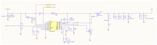
I designed a 28V boost around the LM5122, aiming for a 24V input and output of up to 140W.
I calculated all the parameter values based on the datasheet equations, and also used TI Webench to sanity check my component choices & values.
I have some things upstream of my circuit that I've completely removed from the power path for testing, and I'm putting power directly into the input node now. The behavior I notice is pretty odd - I turn on the power supply and slowly ramp the voltage up.
At around 13V, I hear a buzzing sound (either coming from cap or inductor, not sure) and the circuit outputs ~2v. Increasing the voltage will trip the OCP on the power supply.
- I don't have a load connected other than my scope probe.
- I have confirmed that the VIN pin (3) is properly being pulled up through R402
This behavior is strange to me, because on paper the only current path that could be causing the OCP trip appears to be through Q403.
I'd love some eyes on my schematic, and if I've missed anything obvious or made a silly mistake please point it out!