This thread has been locked.

If you have a related question, please click the "Ask a related question" button in the top right corner. The newly created question will be automatically linked to this question.

TPS25750: I2Cr is not executed

Part Number: TPS25750
Other Parts Discussed in Thread: USB-PD-CHG-EVM-01, , TPS25751, BQ25798

Tool/software:

Hey there,

I am trying to get the I2C master interface of the TPS25750 device working. I am using the USB-PD-CHG-EVM-01 eval board.

Therefore I am executing the following procedure driven by an external generic I2C master:

[R = Read, W = Write]

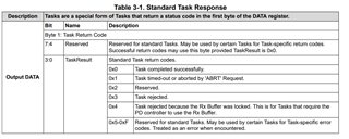
(R) MODE ( == APP ) -> (W) DATA1 (3 Bytes, 0x50 0x4C 0x43) -> (R) DATA1 (first three bytes 0x50 0x4C 0x43. OK continue) -> (W) CMD1 (4 Bytes, 0x49 0x32 0x43 0x72)

                                                              ^ EEPROM (Addr 0x50), Offset 0x4C, Byte count 0x43                                                                                              I       2       C      r

(wait some time. In theory 'poll until CMDComplete is set to 1', but it is never set to 1 as the command is not executed).

(R) CMD1 (4 Bytes, 0x49 0x32 0x43 0x72)

Each of these five steps has a recording from a Logic Analyzer below: (i could not fit them in one big screenshot, but they are one continous recording):

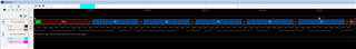
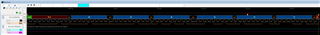
After reading CMD1 back in it is still set to 'I2Cr'. I am also recording the I2C-Master interface of the TPS25750 chip and there is no data sent at all.

This leads me to the conclusion that the TPS is in fact receiving the sent data (as reading the registers CMD1 and DATA1 back in returns the correct data) but is never trying to execute it.

I am expecting the chip to set CMD1 to !CMD if the command string should be wrongly formated (byter order or similar) or try to execute the I2C Master transaction and fail if the DATA1 register should have a faulty value

but none of those two is happening.

Why does the TPS not do anything at all?

Any help would be greatly appreciated.

Greetings, Leo.

  • Some additional notes:

    The only power to the EVM board is an external lab bench power supply with 10V attached to BAT. The TPS then closes the internal FET to also supply SYS with those 10V. From there, LDO_1V5, VSYS, PP_5V and LDO_3V3 generate their appropriate voltages.

    Therefore this can't be any power related issue.

    Also i noted that the TPS seems to not process any command I send to it. If I replace the 'I2Cr' command with something random like 'abcd' the chip also does nothing and doesn't overwrite the CMD1 register with '!CMD'.

    Am I forgetting some step completely that triggers the command execution on the chip?

  • Hi Leonhard, 

    Thank you for reaching out!

    I will review the steps above and get back to you with feedback by Wednesday. 

    Best Regards, 

    Aya Khedr

  • Hi Leonhard, 

    Which version of the GUI are you using to generate the binary/flash the device? 

    I also would like to highlight our follow-on device, the TPS25751. We are recommending the TPS25751 for all new designs. Please see the following FAQ.

    Best Regards, 

    Aya Khedr 

  • Hi Aya,

    I am using the offline GUI version 7.0.4 (the online version did not work because of company IT security settings).

    We already integrate the TPS25751 in our own board, but use the usb-pd-chg-evm-01 board (with TPS25750) while waiting for the prototypes to arrive.

    I made some progress narrowing down the error. If I use a USB-2-ANY I can get the TPS to at least try and send out data on it's internal I2C port. The data is really bugged up though (only one byte is sent out SDA and SCL is switched to low during the start bit but stays low for the whole transmission). I found two simmilar cases in this forum in which the problem was fixed by writing a new full image to the EEPROM generated by tool version 7.0.4. I am currently trying to find an EEPROM programmer or similar to try the newly generated image...

    Best Regards,

    Leonhard Mittermeier

  • Ok so i got some news. I successfully wrote the produced image to the EEPROM and now the TPS25750 correctly responds to the I2Cr commands by setting CMD1 to zero after writing. But now I am getting "Task Rejected" in the Data1 register even though the datasheet doesn't mention that status code as a valid response to I2Cr. What reasons can lead to I2Cr failure and task rejection?

  • Hi Leonhard, 

    Thank you for the updates. See the standard task response table below: 

    I have not seen use-cases where "I2Cr" is used to read the EEPROM. Typically this command is used to read registers from the battery charger. Could you try reading a register from the BQ? Is the task still being rejected in this case?

    Best Regards, 

    Aya Khedr 

  • Hi Aya,

    you're right, the EEPROM read is not really usefull, it was just my first test of the I2Cm module.

    I just tried reading the PART_INFO register from the BQ25798 device, but i got the same result:

    (green: start bit, red: stop bit, orange/.: acknowledge)

    Correct me if I'm wrong, but I guess the read values from register 09 mean 0x40 bytes (64 byte size of the DATA1 register), 0x03 task response code (task rejected).

    For the sake of completeness this is the config file I used to create the EEPROM image from:

    {"questionnaire":{"version":"7.0.4.7","answers":[0,4,4,1,1,1,1,null,1,null,0,8.3,1.5,0.12,0.2],"options":{},"configID":"0000","vendorID":"0000"}}

    Best regards,

    Leonhard Mittermeier

  • Hi Aya, great news. I got the TPS25750 -finally- working as expected.

    Cause of the malfunction was still the EEPROM image. For some reason the .bin file generated by the 'TPS25750 Application Customization Tool' was faulty and caused the malfunction. I stumbled across the 'USBCPD Application Customization Tool' just a minute ago, which happens to also generate a .bin for the TPS25750 with a completely identical user interface as the TPS25750 tool. Plugged in the values, flashed to the EEPROM and everything works like nothing ever happened.

    Seems like there is a bug in the 7.0.4 version of the TPS25750 AppCusTool that is fixed in the USBPD AppCusTool.

    If an TI intern should be interested in analyzing this bug, here are the two .bin files (working/buggy) generated with an identical configuration (see previous comment) in the two tools:

    usb-pd-chg-evm-01-tps25750-bin.zip

    Thanks for your help,

    Leo