This thread has been locked.

If you have a related question, please click the "Ask a related question" button in the top right corner. The newly created question will be automatically linked to this question.

LM5145-Q1: Regulator Output not regulating, Soft start held low even though ILIM is not triggered

Part Number: LM5145-Q1
Other Parts Discussed in Thread: CSD18563Q5A

Tool/software:

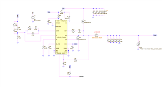
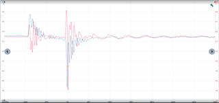
I have designed my circuit as shown below. The circuit works perfectly well in simulation but when testing the designed board, I seem to have an issue where the soft start is held low consistently. My main theory was that there was a load fault where the ILIM signal was somehow going lower than the ILIM threshold noted of 3 mV and I have confirmed that it does not as it sits at about 360 mV with no load. I have also played with the Boostrap resistor and confirmed there isnt any significant ringing that I could see that would cause any issues. Nevertheless, the SS pin is held low and looks like it still under goes a load fault of some kind as I can see an interaction between it and the Feedback pin. See scope capture showing Feedback in Blue and Soft start in red. I also had a look at the compensation network and I do not see any issues there. Is there anything I am missing on this design ?

Thanks for any input!

  • Hi Suliman,

    Pleas send a completed quickstart file for this design. 

    Is it just one board causing the issue? Check that the EN voltage is high. COMP should also be high.

    Note that TO-263 / D2PAK FETs are not great here. Better to use 5 x 6mm package devices. This AOS FET in particular has super high Qrr, which may be contributing to noise issues. https://www.aosmd.com/res/datasheets/AOB66919L.pdf 

    Regards,

    Tim 

  • Also, I see the Fsw is quite high here, so check the VCC current consumption. Each FET has a gate drive current component of Qg*Fsw. It's likely that you are exceeding the VCC current limit.

  • Hi Tim

    Thank you so much for the response, Apologies for the missed relevant information but I have used CSD18563Q5A as my MOSFET (and used the one in the sim as it has similar Rds On) I have checked the VCC pin and it looks to be very stable at 7.5V. I will try and reduce the switching frequency (Currently 400 kHz) to see if anything changes. I am also going to try and add a gate resistor to the low side FET (as I have a bootsrap resistor fitted already of 2.2 Ohm)  and see if things improve.

  • No need to add a gate resistor on the low-side FET - it doesn't really affect the switching (other than slowing up the gate voltage and possiblly causing a spike on the gate voltage when the SW voltage rises). Also, the FETs you use are low QG, so it's not VCC current limit.

    Can you verify the SS pin is not shorted low. Are you seeing this only on one unit or is it multiple parts?

    --

    Tim

  • Yes the soft start pin was absolutely fine, I resolved the issue which was an interesting discovery. The noise on the feedback trace was what caused the "Load fault". I cut the feedback trace and wired it separately such that it did not at any point go under the switching node plane (I made a large plane for thermal reasons) and the issue was resolved. I had not seen anywhere on the datasheet that a load fault which I inferred to be the cause due to the soft start pin being held low could be caused by noise on the feedback pin as the only faults I've seen mentioned are a load fault, UVLO and thermal fault. 

  • Thanks for the information. FB is a critical trace and should be as short as possible (keep the lower FB resistor right across the FB and AGND pins). Also, referring to the layout guidelines in the datasheet, SW should be absolute minimum area. Heatsinking is with the inductor and with copper on the high-side FET drain, not SW copper.

    Regards,

    Tim