


Tool/software:
Hi team,
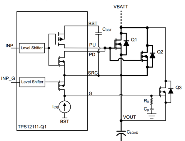
My customer wants to use TPS12111-Q1 to limit the inrush current and have questions about the precharge function.
They use 2 MOSFETs connected in parallel as the main FETs. In their application, the load capacitor is 2mF, the inrush current is about 100A and the max nominal current is about 89A. When the voltage of the capacitor is above a specific level, like 7V or 8V, the load will start to drawing current and then discharging the capacitor voltage. The precharge FET will need to tolerate a large current, which may damage the FET.
They now use TPS12110-Q1 on their board and reserve the design of TPS12111-Q1. They want to know whether it is feasible to add Rg and Cg to the gate of the main FETs (Q1 and Q2). According to the datasheet, it is not recommended, because the 2 FETs may have different parameters and will suffer different inrush current.
Do we have any experience in similar applications? Compared with adding Rg and Cg to the gate of the main FETs, Is there a better way to limit the inrush current in such scenario? Note that the end use case is zonal control module and customer do not have a clear idea starting from which voltage threshold the output will discharge, so they'll not be able to control INP and INP_G with output voltage monitoring, and there's no current sensing at pre-charge path.
also would you pls share guidance how we get below equation 3)? the goal is to understand whether we could support enough current to overcome miller region with parallel FETs.

Thanks
Scarlett